dumpspedia logo

Which state in the adjacency process do OSPF routers check the MTU size?
Init
Exchange
Done
ExStart
In OSPF, routers exchange link-state information in different stages to establish full adjacency. The MTU size is checked during the Exchange state.
Step-by-Step Breakdown:
1. OSPF Adjacency Process:
o OSPF routers go through multiple stages when forming an adjacency: Down, Init, 2-Way, ExStart, Exchange, Loading, and Full.
2. Exchange State:
o During the Exchange state, OSPF routers exchange Database Description (DBD) packets to describe their link-state databases. The MTU size is checked at this stage to ensure both routers can successfully exchange these packets without fragmentation.
o If there is an MTU mismatch, the routers may fail to proceed past the Exchange state.
Juniper Reference:
· MTU Checking in OSPF: Junos uses the Exchange state to check for MTU mismatches, ensuring that routers can properly exchange database information without packet fragmentation issues.
You have configured nonstop active routing NSR and want to verify the status of the synchronization including which protocols are configured for NSR support. Which command would you use to accomplish this task?
show task replication
show system services
show system switchover
show services ha statistics
Nonstop active routing relies on control-plane state synchronization between the primary and backup Routing Engines so that routing protocol operation can continue across a switchover. To verify whether that synchronization is occurring and to see which protocol processes are participating, Junos provides visibility into the underlying replication framework. The command show task replication displays replication status and synchronization details for replicated tasks, which commonly include routing-related processes when NSR is enabled. This output helps confirm whether the backup Routing Engine is receiving the necessary state updates and whether replication is in sync, catching up, or experiencing issues.
This is the most direct operational validation because NSR effectiveness depends on ongoing state replication. Simply checking general switchover readiness does not prove protocol state is synchronized. Likewise, listing system services does not confirm replication or identify which routing protocols are actively supported for nonstop behavior. High availability statistics under services are oriented toward service-specific HA functions and do not provide the routing protocol replication view that NSR troubleshooting typically requires.
In data center fabrics where underlay routing stability is critical, routinely checking task replication status is a practical way to verify that NSR is actually providing the intended resilience before you perform maintenance or experience an unplanned Routing Engine event.
Verification sources from Juniper documentation
https://www.juniper.net/documentation/us/en/software/junos/high-availability/topics/topic-map/nonstop-active-routing-understanding.html
https://www.juniper.net/documentation/us/en/software/junos/high-availability/topics/reference/command/show-task-replication.html
What are three correct layer names used in legacy hierarchical network design? (Choose three.)
Access layer
Modular layer
Aggregation layer
Core layer
Function layer
In legacy hierarchical network design, three key layers are used to create a scalable and structured network:
Step-by-Step Breakdown:
Access Layer:
The access layer is where end devices, such as computers and IP phones, connect to the network. It typically involves switches that provide connectivity for devices at the edge of the network.
Aggregation Layer (Distribution Layer):
The aggregation layer (also called the distribution layer) aggregates traffic from multiple access layer devices and applies policies such as filtering and QoS. It also provides redundancy and load balancing.
Core Layer:
The core layer provides high-speed connectivity between aggregation layer devices and facilitates traffic within the data center or between different network segments.
Juniper Reference:
Legacy Hierarchical Design: Juniper networks often follow the traditional three-layer design (Access, Aggregation, and Core) to ensure scalability and high performance.
Which BGP attribute is used to prevent routing loops in a network?
MED
LOCAL_PREF
NEXT_HOP
AS_PATH
BGP prevents inter-domain routing loops primarily through the AS_PATH attribute. Each time a route advertisement crosses an autonomous system boundary, the advertising router prepends its own AS number to the AS_PATH before sending the route onward. When a router receives a BGP update, it can inspect the AS_PATH and reject routes that already contain its own AS number. This simple rule blocks the route from circulating back into the same AS, which is the fundamental loop prevention behavior in BGP.
In data center IP fabrics that use EBGP for the underlay, AS_PATH still plays an important role even though private AS numbers are used. The fabric can be designed so that leaf and spine devices are in distinct private ASs or use structured AS assignment, and AS_PATH tracking ensures clean propagation and helps operators understand where a route has traveled. It also supports policy decisions, such as preferring shorter paths or applying policy based on specific AS sequences.
The other attributes serve different purposes. MED influences inbound path selection into an AS, LOCAL_PREF is used within an AS to influence outbound selection, and NEXT_HOP indicates the forwarding next hop and is validated for reachability. None of those attributes provide the explicit “contains my AS” loop detection that AS_PATH does.
You are asked to ensure that traffic and routing information is not interrupted if your primary Routing Engine fails or switches to the backup Routing Engine. In this scenario, which high availability feature will accomplish this behavior?
nonstop active routing NSR
graceful Routing Engine switchover GRES
link aggregation control protocol LACP
bidirectional forwarding detection BFD
Nonstop active routing is the Junos high availability capability that focuses on preserving routing protocol operation and routing information across a Routing Engine switchover. In platforms with redundant Routing Engines, a failure of the primary Routing Engine can otherwise reset routing protocol processes, tear down adjacencies, and trigger reconvergence. NSR mitigates this by synchronizing routing protocol state so that the backup Routing Engine can continue routing protocol operations with minimal disruption. This includes maintaining protocol session continuity and keeping the routing information base stable, which directly protects traffic that depends on those routes.
In data center environments, this is particularly important for routed fabrics where BGP or OSPF underlay reachability supports overlay services and east west application traffic. By keeping routing information consistent during the control-plane transition, NSR reduces route churn and helps avoid transient blackholing or microbursts caused by reconvergence.
GRES is closely related but addresses a different scope. GRES helps the forwarding plane continue forwarding during a Routing Engine switchover by preserving certain system and interface states. However, GRES alone does not guarantee that routing protocol sessions and routing information remain uninterrupted. BFD and LACP are valuable availability tools, but they are not Routing Engine redundancy features and do not preserve routing state during a Routing Engine failover.
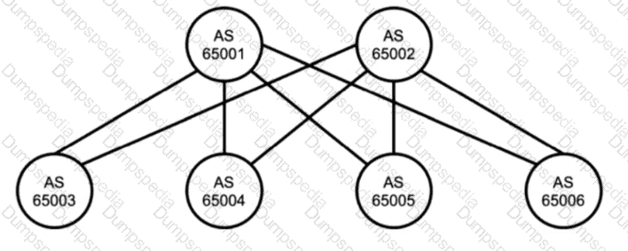
Referring to the exhibit, which two statements are true about BGP? Choose two.
The exhibit uses IBGP.
Devices should peer using loopback addresses.
The exhibit uses EBGP.
Devices should peer using physically connected IP addresses.
The diagram shows multiple autonomous systems, with each device labeled with a different AS number. Because the peers are in different autonomous systems, the correct BGP session type is external BGP. In a typical Juniper data center IP fabric underlay, this design is intentional: EBGP is used between leaf and spine devices to simplify policy boundaries, improve operational clarity, and avoid the additional mechanisms commonly required in large internal BGP designs.
In an EBGP-based underlay, neighbors are most commonly formed over the directly connected point-to-point links between leaf and spine. That means the BGP peering is established using the IP addresses configured on those physical routed interfaces, not loopback addresses. Using physically connected addresses aligns with the default EBGP behavior where the TTL is one hop, and it reduces configuration complexity because no multihop settings or additional reachability dependencies are required to bring up the session.
Peering using loopbacks is possible, but it typically requires EBGP multihop and a routing method to ensure reachability to the remote loopback before BGP can establish. That approach is more common for overlay control-plane sessions or for specific design requirements, rather than for the simplest and most common underlay implementation. Therefore, the two true statements are that the exhibit uses EBGP and that devices should peer using physically connected IP addresses.
Which protocol is supported in an IP fabric underlay network? Choose one.
RSTP
EVPN
VXLAN
EBGP
An IP fabric underlay is the routed foundation of a modern leaf-spine data center. Its purpose is to provide scalable, deterministic Layer 3 reachability between all fabric nodes, typically using point-to-point routed links between leaves and spines. In this design, EBGP is commonly used as an underlay routing protocol because it scales well, supports clear policy boundaries, and enables fast convergence and operational simplicity. Each leaf forms EBGP sessions to each spine, advertising loopback addresses and link subnets so that overlay endpoints and control plane services can reach one another reliably.
RSTP is a Layer 2 spanning tree mechanism and is not the standard protocol for a routed underlay. EVPN is an overlay control plane used to distribute tenant reachability and multihoming information; it is not the underlay routing protocol itself. VXLAN is a data plane encapsulation used by the overlay to transport Layer 2 segments across a Layer 3 fabric; it also is not the underlay routing protocol.
In Juniper data center architectures, the underlay is intentionally kept simple and purely routed, while overlays such as EVPN VXLAN deliver multi-tenant Layer 2 and Layer 3 services on top of that underlay. EBGP fits the underlay requirement among the provided options.
Which two statements are correct about an underlay IP fabric in a data center? Choose two.
All fabric devices must be the same model to ensure that traffic is distributed across physical connections.
ECMP load balancing ensures that traffic is distributed across physical connections.
Routing protocols are used to prevent loops when multiple paths exist.
Spanning tree protocols are used to prevent loops when multiple paths exist.
A data center underlay IP fabric is a routed leaf-spine network designed to provide scalable Layer 3 connectivity between all fabric nodes. A key property of these fabrics is that there are multiple equal-cost paths between any two endpoints, typically across multiple spine devices. Equal-Cost Multi-Path load balancing is used to distribute traffic across those parallel paths. The routing table installs multiple next hops for the same destination prefix, and the forwarding plane selects an egress link per flow using a hash, which keeps packets in-order within a flow while using the fabric’s aggregate bandwidth. This makes statement B correct.
Because the underlay is routed, loop avoidance is handled by the routing protocol and the fundamental properties of IP forwarding, not by spanning tree. Routing protocols compute a loop-free forwarding topology and use mechanisms like shortest-path calculation and next-hop selection so that even when multiple paths exist, traffic is forwarded along valid loop-free routes. This makes statement C correct. Statement D is incorrect because spanning tree is a Layer 2 loop prevention mechanism and is not required or desired in a routed underlay fabric. Statement A is also incorrect because traffic distribution depends on ECMP and forwarding behavior, not on all devices being the same hardware model. Mixed platforms can interoperate as long as the design accounts for capacity, features, and consistent routing behavior.
What is a function of an integrated routing and bridging IRB interface?
to route traffic between different VLANs
to encrypt traffic between network segments
to bridge traffic within the same VLAN
to provide Network Address Translation NAT
In Junos-based data center switching, an IRB interface is the Layer 3 gateway that is logically associated with a Layer 2 VLAN or bridge domain. The VLAN provides Layer 2 bridging inside the broadcast domain, while the IRB interface provides the routed interface that enables hosts in that VLAN to reach destinations outside their local subnet. This is the standard mechanism used for inter-VLAN routing on Juniper switches and for providing default gateway services to servers connected to access ports or VLAN-tagged trunks.
Operationally, endpoints in a VLAN use the IRB interface IP address as their default gateway. Frames destined to a remote subnet are bridged at Layer 2 to the IRB gateway MAC address, and then the packet is routed at Layer 3 based on the routing table. This allows a single device to perform both bridging within the VLAN and routing between VLANs or to other routed interfaces, which is why the concept is called integrated routing and bridging.
IRB does not encrypt traffic and does not provide NAT by itself; those functions are typically associated with security services features and firewall platforms. IRB is also not the mechanism that performs pure bridging within the same VLAN, because bridging is handled by the VLAN or bridge domain and the Ethernet switching table.
What are two BGP message types? Choose two.
open
hello
update
LSA
BGP uses a small set of well-defined message types to form and maintain peerings and to exchange routing information. The Open message is used during session establishment after the TCP connection is up. It communicates the parameters required to form the BGP session, such as the BGP version, the autonomous system number, the negotiated hold time, the BGP identifier, and optional capabilities. Capabilities are especially important in data center designs because they enable features such as 4 byte ASNs, route refresh, and EVPN signaling when applicable.
The Update message is the core mechanism BGP uses to advertise reachability and to withdraw routes that are no longer valid. In a data center underlay using EBGP, Update messages carry the prefixes that represent loopbacks and point-to-point links, enabling leaf and spine reachability. In an EVPN control plane, Update messages carry EVPN Network Layer Reachability Information to distribute MAC and IP reachability and multihoming information across the fabric.
Hello is not a BGP message type. Hello is commonly associated with protocols like OSPF, IS-IS, and some discovery mechanisms. LSA is not a BGP message type either; Link State Advertisements are specific to OSPF.
What are two characteristics of EBGP? Choose two.
EBGP sessions do not require an IGP.
EBGP sessions require loopback IP address peering.
EBGP does not support sessions with non-directly connected peers.
EBGP sessions are typically established between directly connected peers.
EBGP is the BGP session type formed between different autonomous systems. In Juniper data center IP fabrics, EBGP is frequently used for the underlay because it can provide all required reachability without an additional interior gateway protocol. The fabric can advertise loopbacks and point-to-point link subnets directly in BGP, then use ECMP to install multiple equal-cost next hops. This is why EBGP sessions do not require an IGP as a fundamental dependency. Some designs still add an IGP for other reasons, but EBGP itself can carry the underlay routes needed for full fabric connectivity.
EBGP sessions are also typically established between directly connected peers. In a standard leaf-spine underlay, each leaf peers with each spine over the routed physical links between them, using the interface IP addresses on those point-to-point subnets. This matches EBGP default behavior, including a one-hop TTL expectation and straightforward operational troubleshooting.
Loopback peering is not required for EBGP. It is possible, but it usually needs additional configuration such as multihop and a routing method to ensure reachability to the remote loopback before the BGP session can form. EBGP also supports sessions with non-directly connected peers when multihop is configured, so it is incorrect to claim EBGP does not support that capability.
You are creating an IP fabric underlay and want to use OSPF as your routing protocol.
In this scenario, which statement is correct?
All leaf devices must be configured in separate OSPF areas.
All leaf and spine devices must be the same model to ensure the proper load-balancing behavior.
Interface speeds should be the same throughout the fabric to ensure that all links are utilized.
All spine devices must use the same router ID.
When creating an IP fabric underlay using OSPF as the routing protocol, consistent interface speeds are important to ensure optimal traffic distribution and utilization of all links.
Step-by-Step Breakdown:
OSPF and Interface Speeds:OSPF calculates the cost of a link based on its bandwidth. The default cost calculation in OSPF is:

If interface speeds vary significantly, OSPF may choose paths with lower cost (higher bandwidth), resulting in some links being underutilized.
Equal Utilization:To ensure that all links are equally utilized in an IP fabric, it is recommended to maintain uniform interface speeds across the fabric. This ensures balanced load sharing across all available paths.
Juniper Reference:
IP Fabric with OSPF: Juniper recommends consistent interface speeds to maintain even traffic distribution and optimal link utilization in IP fabric underlay designs.
What is the default route preference of a static route in the Junos OS?
0
10
1
5
In Junos OS, the default route preference for a static route is 5. Route preference values are used to determine which route should be installed in the routing table when multiple routes to the same destination are available.
Step-by-Step Breakdown:
Static Route Preference:
A static route, by default, has a preference of 5, making it a highly preferred route. Lower preference values are more preferred in Junos, meaning static routes take precedence over most dynamic routing protocol routes, such as OSPF (preference 10) or BGP (preference 170).
Route Preference:
Route preference is a key factor in the Junos routing decision process. Routes with lower preference values are preferred and installed in the forwarding table.
Juniper Reference:
Static Routes: In Junos, the default preference for static routes is 5, making them more preferred than most dynamic routes.
According to Juniper Networks, the bridge table is more commonly known as a _________.
forwarding table
forwarding bridge
bridging information table
forwarding information table
In Ethernet switching, the bridge table is the data structure that maps MAC addresses to the switch interfaces where those MAC addresses were learned. Juniper commonly describes this function as the Ethernet switching table and also refers to it as the forwarding table in Layer 2 contexts. The concept is the same: the switch learns source MAC addresses from incoming frames, associates them with an ingress port and VLAN or bridge domain, and then uses that learned information to forward future frames to the correct egress port as known unicast.
Calling it a forwarding table is accurate because its primary operational purpose is deciding how to forward Layer 2 frames efficiently. When a destination MAC is present in the table, the switch performs a unicast forward to the learned port. When a destination MAC is not present, the switch treats it as unknown unicast and floods it within the VLAN or bridge domain, while still learning the source MAC for future use.
The term forwarding information table is more strongly associated with Layer 3 routing, where a FIB represents resolved next hops for IP prefixes in the forwarding plane. That is a different structure than the Layer 2 bridge or MAC table. The other options are not standard Juniper terms for this function.
Verification sources from Juniper documentation
https://www.juniper.net/documentation/us/en/software/junos/multicast-l2/topics/topic-map/ethernet-switching-components.html
https://www.juniper.net/documentation/us/en/software/junos/multicast-l2/topics/concept/ethernet-switching-table-understanding.html
Which statement is correct about nonstop bridging? Choose one.
Graceful Routing Engine switchover is required.
It preserves Layer 3 information and protocol sessions.
Nonstop active routing is required.
The gigether-options flow-control parameter is required.
Nonstop bridging is a high availability capability focused on maintaining Layer 2 switching continuity during a Routing Engine switchover on platforms that support redundant control planes. The intent is to keep Layer 2 forwarding operational and minimize disruption to bridged traffic when the system transitions from a primary to a backup Routing Engine. Achieving this requires Graceful Routing Engine switchover, because GRES is the mechanism that enables a control plane switchover while keeping forwarding and interface state stable. With GRES in place, the forwarding plane can continue switching frames while the backup Routing Engine assumes control, reducing or eliminating traffic loss for Layer 2 domains.
Nonstop bridging is not the feature that preserves Layer 3 protocol sessions and routing information end-to-end. That function is associated with nonstop routing capabilities, which focus on maintaining routing protocol state across Routing Engine events. Therefore, stating that nonstop bridging preserves Layer 3 information and protocol sessions is incorrect. Likewise, nonstop active routing is not a requirement for nonstop bridging; it is a separate feature aimed at routing stability. The flow-control setting under gigether-options is unrelated to Routing Engine redundancy and does not determine whether nonstop bridging operates.
In data center access and aggregation environments where VLANs must remain stable for servers and appliances, nonstop bridging paired with GRES helps protect Layer 2 service continuity during control plane events.
Which two statements about VLANs are true? Choose two.
By default, ports in a VLAN operate in trunk mode.
A single VLAN is limited to only half of a switch's physical ports.
A single VLAN can include all of a switch's physical ports.
By default, ports in a VLAN operate in access mode.
In Junos Ethernet switching, a VLAN is a Layer 2 broadcast domain and can include any set of switch ports that you assign to it. There is no generic rule that limits a VLAN to only half of a switch’s physical ports. Practically, a single VLAN can include all physical ports on the switch if that is how the environment is designed, for example in a flat Layer 2 segment for a specific purpose or during a migration. This makes statement C correct.
For interface mode behavior, access mode is the default expectation for endpoint-facing Layer 2 ports where traffic is normally untagged. In Junos, when an interface is configured for Ethernet switching and no explicit trunk configuration is applied, the operational intent aligns with access behavior: the port is associated with a single VLAN and forwards frames as untagged on the wire. Trunk mode must be explicitly configured when the link needs to carry multiple VLANs using 802.1Q tagging, such as switch-to-switch uplinks or server connections that tag multiple VLANs. Therefore, statement D is correct and statement A is incorrect because trunk mode is not the default behavior.
This distinction is important in data center operations because misidentifying an access port as a trunk can lead to dropped traffic, VLAN mismatch, or unexpected flooding behavior.
Verification sources from Juniper documentation
https://www.juniper.net/documentation/us/en/software/junos/multicast-l2/topics/topic-map/bridging-and-vlans.html
https://www.juniper.net/documentation/us/en/software/junos/multicast-l2/topics/task/interfaces-configuring-ethernet-switching-access.html
You want your Junos OS router to drop packets that it receives for a particular destination IP address. You also want to notify the source of the traffic that the destination IP address is unreachable. How would you accomplish this task?
Create a static route for the destination IP address in the inet.3 routing table.
Add the destination IP address to the list of martian IP addresses.
Create a static route for the destination IP address with a next hop of reject.
Create and apply a firewall filter to the ingress interface that discards traffic destined to the IP address.
To intentionally drop traffic to a specific destination while also informing the sender that the destination is unreachable, Junos provides a routing action specifically meant for this behavior: a static route with a next hop of reject. A reject route installs a forwarding entry that causes matching packets to be dropped, and it also triggers generation of an ICMP unreachable message back to the traffic source. This is useful in data center routing for controlled blackholing with feedback, for example when you want to signal misrouted traffic, invalid destinations, or to enforce policy with explicit notification.
A discard route also drops packets, but it does so silently without sending ICMP unreachable messages. That makes discard appropriate for traffic-sink use cases such as safe summarization or DDoS mitigation where you do not want to generate return traffic. Adding addresses to martians is intended to block invalid special-use prefixes from being treated as routable, not to create a targeted unreachable response for an arbitrary destination. Using inet.3 is related to MPLS label-switched forwarding and does not address the requirement. A firewall filter that discards traffic will typically drop silently unless explicitly configured to send rejects in a security context, and it is not the standard routing-table-based method when the requirement is an ICMP unreachable response for a destination prefix.
Therefore, a reject static route is the correct solution.


TESTED 14 Oct 2026