dumpspedia logo

You are using Juniper Apstra to create security policies that create ACLs on the fabric devices. What are two valid objects that would be used within Apstra in this scenario? (Choose two.)
Virtual network
Domain name
Routing zone
Application signature
In Apstra 5.1, Security Policies express traffic-permit/deny intent between defined fabric endpoints, and Apstra compiles that intent into ACL enforcement on the appropriate switches (for example, on gateway interfaces for east-west segmentation and on border leaf interfaces for north-south controls). The objects you use to define that policy intent must correspond to fabric connectivity constructs that Apstra understands as endpoints in the blueprint’s logical model.
Two such valid objects are Virtual Networks and Routing Zones. A virtual network represents a tenant segment (typically mapped into EVPN-VXLAN constructs such as VNI and associated IRB gateway when L3 is enabled). Policies between virtual networks are a common way to implement micro-segmentation or tier-based segmentation (web/app/db) within the same tenant boundary. A routing zone represents the L3 tenancy boundary (mapped to a VRF) and can be used to group and control connectivity at the tenant level, especially where policy needs to be expressed for aggregated tenant domains or for controls involving external connectivity.
“Domain name” and “application signature” are not endpoint objects for Apstra Security Policies in this context. They may exist in other security ecosystems, but Apstra’s security intent model for ACL generation is based on topology and blueprint objects (routing zones, virtual networks, and endpoint definitions), which can then be rendered into Junos v24.4 firewall filter–style enforcement on the fabric devices.
Verified Juniper sources (URLs):
https://www.juniper.net/documentation/us/en/software/apstra5.1/apstra-user-guide/topics/topic-map/policy-security.html
https://www.juniper.net/documentation/us/en/software/apstra5.1/apstra-user-guide/topics/concept/routing-zones.html
https://www.juniper.net/documentation/us/en/software/apstra5.1/apstra-user-guide/topics/concept/virtual-networks.html
You want to route between tenants in a multitenant environment in Juniper Apstra. What are two ways to accomplish this task? (Choose two.)
Route between VRFs on a VTEP-enabled device.
Use an external device to route between tenants.
Use iBGP to route within the same AS number.
Use virtual networks to route between VRFs.
In Apstra 5.1 multitenancy, tenants are modeled as routing zones, and each routing zone maps to a distinct VRF to provide strict Layer 3 isolation. Because each tenant’s VRF is separate, “routing between tenants” is effectively inter-VRF routing. Apstra’s routing-zone behavior emphasizes that inter-tenant routing is achieved via external systems: you connect each tenant/routing zone to an external router or firewall (often attached to border leafs), and that external device performs the policy-controlled inter-VRF routing between tenants. This approach is the most common because it centralizes security and compliance controls (stateful inspection, zone policies, NAT, logging) on the firewall/router while keeping the fabric clean and consistent.
A second method is to perform inter-VRF routing on a VTEP-capable border leaf that terminates the tenant VRFs. In EVPN-VXLAN designs, border leafs are frequently the demarcation where tenant VRFs connect to outside domains; when the same border leaf hosts multiple tenant VRFs and is designed to provide L3 services for them, it can act as the routing point between VRFs (subject to your design and security requirements). Junos v24.4 supports VRFs and policy constructs required for controlled route exchange and forwarding behavior, but Apstra’s intent model still expects routing-zone isolation by default—so any inter-tenant connectivity should be explicitly designed and governed, typically at the border.
Which two actions are required during Juniper Apstra's deploy phase? (Choose two.)
Assign device profiles to the blueprint.
Assign user roles to the blueprint.
Assign interlace maps to the blueprint.
Assign resources to the blueprint.
The deploy phase is the final step in the Juniper Apstra data center fabric design and deployment process. In this phase, you apply the Apstra-rendered configuration to the devices and verify the intent of the blueprint. Based on the web search results, we can infer the following actions are required during the deploy phase12:
Assign device profiles to the blueprint. This action associates a specific vendor model to each logical device in the blueprint. Device profiles contain extensive hardware model details, such as form factor, ASIC, CPU, RAM, ECMP limit, and supported features. Device profiles also define how configuration is generated, how telemetry commands are rendered, and how configuration is deployed on a device. Device profiles enable the Apstra system to render and deploy the configuration according to the Apstra Reference Design34.
Assign resources to the blueprint. This action allocates the physical devices, IP addresses, VLANs, and ASNs to the logical devices, networks, and routing zones in the blueprint. Resources can be assigned manually or automatically by the Apstra system. Assigning resources ensures that the blueprint has all the necessary elements to generate the configuration and deploy the fabric5 .
Assign user roles to the blueprint. This action is not required during the deploy phase. User roles are defined at the system level, not at the blueprint level. User roles determine the permissions and access levels of different users in the Apstra system. User roles can be system-defined or custom-defined .
Assign interface maps to the blueprint. This action is not required during the deploy phase. Interface maps are defined at the design phase, not at the deploy phase. Interface maps are objects that map the logical interfaces of a logical device to the physical interfaces of a device profile. Interface maps enable the Apstra system to generate the correct interface configuration for each device in the fabric . References:
Deploy
Deploy Device
Device Profiles
Juniper Device Profiles
Resources
You are performing an upgrade to your switches in your network. You want to ensure that the upgrade can be performed without interrupting traffic. In the Juniper Apstra UI, which deploy mode should be used to accomplish this task?
Deploy
Undeploy
Drain
Ready
In Apstra, Deploy Mode = Drain is the operational mechanism used to gracefully remove a switch from active forwarding before performing maintenance such as an OS upgrade. Drain mode is specifically intended to drain traffic while preserving fabric stability, so that maintenance can be executed with minimal to no application impact, provided the fabric design has sufficient redundancy (for example, ECMP in the underlay and dual-homing/ESI for server attachments). In an EVPN-VXLAN IP fabric, taking a leaf or spine abruptly out of service can cause transient loss of reachability as underlay adjacencies reconverge and the overlay recalculates paths. By placing the device into Drain, Apstra adjusts intent so that traffic is shifted away from the device as much as possible, reducing dependency on it before the upgrade begins.
This is different from Undeploy, which removes Apstra-rendered configuration and is generally used for decommissioning; if a device is carrying traffic, Apstra guidance is to drain first. Ready is a pre-deploy state used in lifecycle workflows, not a maintenance traffic-shifting mode. Deploy keeps the device fully participating. Therefore, for a maintenance window where the goal is “upgrade with minimal interruption,” the correct mode is Drain, then perform the Junos v24.4 upgrade, and finally return the device to Deploy.
Verified Juniper sources (URLs):
https://www.juniper.net/documentation/us/en/software/apstra4.2/apstra-drain-mode/apstra-drain-mode.pdf
https://www.juniper.net/documentation/us/en/software/apstra4.2/apstra-user-guide/topics/topic-map/deploy-mode-update-datacenter.html
https://www.juniper.net/documentation/us/en/software/apstra6.0/apstra-user-guide/topics/topic-map/device-config-lifecycle.html
You are using Juniper Apstra to create logical devices and interface maps. You use them in three different rack types. You then modify the logical devices to support the required increased interface speeds and receive an error message when updating the logical devices.
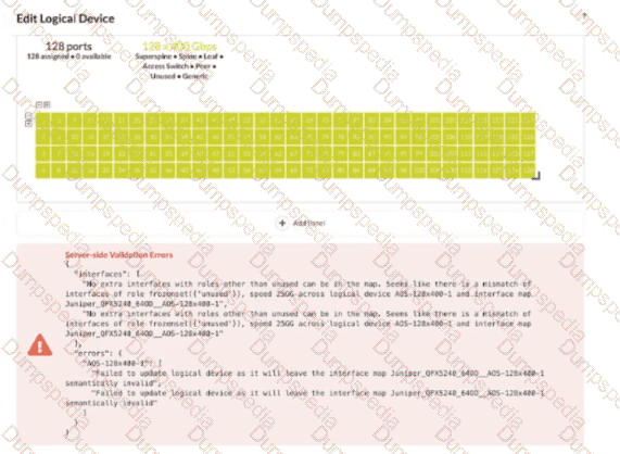
Referring to the exhibit, which action is needed to remove the error?
Remove any templates that reference the logical device.
Remove any interface maps that reference the logical device.
Remove any racks that reference the logical device.
Remove any templates, racks, and interface maps that reference the logical device.
In Apstra 5.1, a logical device defines the abstract port layout and capabilities (including supported speeds), while an interface map binds that abstract port layout to the real, vendor-specific front-panel ports. Rack types then consume logical devices and interface maps to model the rack’s leaf/superspine roles. Once a logical device is referenced by interface maps and used inside rack types (and potentially templates that instantiate those rack types), Apstra treats the combination as a consistent contract: port counts, roles, and speeds must remain semantically valid for every object that depends on it.
The exhibit’s validation error indicates that after changing interface speeds on the logical device, the existing interface map(s) and their usage in rack types no longer match the logical device definition (for example, the map expects certain ports/speeds/roles, but the updated logical device would leave the map invalid). Because the logical device is being consumed in multiple places, the safest and required way to remove the error is to remove all dependencies—templates (if they reference the rack types), rack types, and interface maps—so Apstra can accept the new logical device definition without violating existing mappings. After updating the logical device, you then recreate or update the interface maps and re-associate them with the rack types/templates so the entire chain remains consistent under the new speed requirements.
Within Managed Devices in the Juniper Apstra Ul, you notice that several devices have the OOS-Quarantined status. The devices cannot be added to any blueprint. Which action would solve this problem?
Acknowledge the device.
Fix the hardware issues with the quarantined devices.
Install the agent, even though connectivity is established.
Upload a new pristine configuration.
When an agent installation is successful, devices are placed into the Out of Service Quarantined (OOS-QUARANTINED) state using the Juniper Apstra UI. This state means that the device is not yet managed by Apstra and has not been assigned to any blueprint. The device configuration at this point is called Pristine Config. To make the device ready for use in a blueprint, you need to acknowledge the device, which is a manual action that confirms the device identity and ownership. Acknowledging the device changes its status to Out of Service Ready (OOS-READY)12. References:
Managing Devices
AOS Device Configuration Lifecycle
What does clicking the indicated icon shown in the exhibit accomplish?
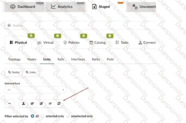
It refreshes the screen.
It fetches the discovered Link Layer Discovery Protocol (LLDP) data.
It erases the entire cable map to start over.
It changes the speed of existing links.
In Apstra 5.1, the Staged > Physical > Links workspace is where you build and validate the cabling (link) intent for the fabric before committing changes. During deployment and day-0/1 build, Apstra can leverage LLDP neighbor discovery from the connected devices to accelerate and validate the cabling map. The indicated toolbar icon in the Links view is used to fetch discovered LLDP data from the devices so Apstra can compare the discovered neighbor relationships with the intended topology and, depending on workflow, help populate or validate link endpoints.
This is particularly important in leaf-spine IP fabrics because correct physical connectivity underpins the entire underlay—interface states, point-to-point addressing, and BGP sessions. In an EVPN-VXLAN design running Junos v24.4, broken or mis-cabled links quickly manifest as missing underlay adjacencies and failed EVPN control-plane signaling. Pulling LLDP discovery into Apstra helps you identify mismatches early (wrong neighbor, wrong port, missing neighbor) and reduces manual cabling errors.
This action is not merely a UI refresh, it does not wipe the cable map, and it does not modify link speeds. Its operational purpose is to import discovered LLDP neighbor information into the blueprint’s physical link view so Apstra can assist with accurate topology validation and deployment readiness.
Exhibit.
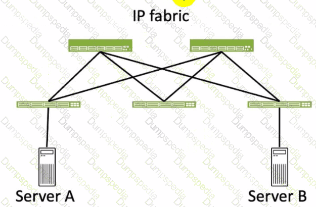
Referring to the exhibit, how many broadcast domains will an Ethernet frame pass through when traversing the IP fabric from Server A to Server B?
1
4
2
3
Referring to the exhibit, the image shows a simplified diagram of an IP fabric network connecting two servers, labeled as Server A and Server B. The IP fabric is a network architecture that uses a Clos topology to provide high bandwidth, low latency, and scalability for data center networks. The IP fabric consists of spine and leaf devices that use BGP as the routing protocol and VXLAN as the overlay technology1.
A broadcast domain is a logical portion of a network where any device can directly transmit broadcast frames to other devices at the data link layer (OSI Layer 2). A broadcast frame is a frame that has a destination MAC address of all ones (FF:FF:FF:FF:FF:FF), which means that it is intended for all devices in the same broadcast domain. A broadcast domain is usually bounded by a router, which does not forward broadcast frames to other networks2.
In the exhibit, there are two broadcast domains that an Ethernet frame will pass through when traversing the IP fabric from Server A to Server B. The first broadcast domain is the one that contains Server A and the leaf device that it is connected to. The second broadcast domain is the one that contains Server B and the leaf device that it is connected to. The IP fabric itself is not a broadcast domain, because it uses IP routing and VXLAN encapsulation to transport the Ethernet frames over the Layer 3 network. Therefore, the statement C is correct in this scenario.
The following three statements are incorrect in this scenario:
A. 1. This is not true, because there are not one, but two broadcast domains that an Ethernet frame will pass through when traversing the IP fabric from Server A to Server B. The IP fabric itself is not a broadcast domain, because it uses IP routing and VXLAN encapsulation to transport the Ethernet frames over the Layer 3 network.
B. 4. This is not true, because there are not four, but two broadcast domains that an Ethernet frame will pass through when traversing the IP fabric from Server A to Server B. The spine devices and the leaf devices that are not connected to the servers are not part of the broadcast domains, because they use IP routing and VXLAN encapsulation to transport the Ethernet frames over the Layer 3 network.
D. 3. This is not true, because there are not three, but two broadcast domains that an Ethernet frame will pass through when traversing the IP fabric from Server A to Server B. The IP fabric itself is not a broadcast domain, because it uses IP routing and VXLAN encapsulation to transport the Ethernet frames over the Layer 3 network.
You are allowed to assign tags for which three objects? (Choose three.)
Virtual networks
Interfaces
Generic systems
Property sets
Device profiles
In Apstra, tags are an intent-level metadata mechanism used to classify objects and drive automation and reuse. Within a data center blueprint, Apstra supports tagging multiple blueprint objects so operators can apply configuration or policy logic conditionally (for example, applying a connectivity template or a configlet based on a tag match). In this scenario, three valid taggable objects are virtual networks, interfaces, and generic systems.
Virtual network tagging is supported directly from the blueprint’s virtual network table, enabling you to label virtual networks (such as “finance,” “pci,” or “dev”) and then reference those tags elsewhere in blueprint operations and policy application. Interface tagging is also explicitly supported in the blueprint, allowing you to assign tags to switch interfaces and use those tags to control how templates, assignments, or other intent-driven operations apply to those ports. Finally, generic systems (which are modeled endpoint systems such as servers or external routers represented as “systems” in the blueprint) can be tagged so that downstream intent logic can distinguish system roles and apply the correct operations consistently across expansions and changes.
By contrast, property sets are structured data objects used for variable substitution and probe/configlet parameterization, not a primary target for operational tagging in the blueprint UI; and device profiles are catalog artifacts describing hardware/NOS compatibility rather than blueprint objects typically tagged for intent application.
Verified Juniper sources (URLs):
https://www.juniper.net/documentation/us/en/software/apstra5.1/apstra-user-guide/topics/topic-map/tag-interface-add-remove-datacenter.html
https://www.juniper.net/documentation/us/en/software/apstra5.0/apstra-user-guide/topics/task/tag-virtual-network-update.html
https://www.juniper.net/documentation/us/en/software/apstra5.0/apstra-user-guide/topics/topic-map/tag-system-add-remove-freeform.html
In Juniper Apstra, which statement about resources is correct?
User-defined resources are supported.
The scope of a pool is limited to a single blueprint.
The scope of a pool can be defined as global or blueprint specific.
Only the default resources are supported globally.
In Apstra 5.1, “resources” are the identifier values consumed by the fabric design and rendered into device configuration—examples include ASNs, IP addresses, VNIs, VLAN-related identifiers (where applicable), and similar allocation-driven values. These values are provided through resource pools, which are the authoritative containers Apstra draws from when assigning resources to blueprint roles (for example, leaf ASNs, spine ASNs, loopbacks, point-to-point subnets, and VNI ranges). A key architectural feature is that resource pools are not confined to one blueprint. Apstra supports pools with different scopes to match operational needs: some pools are managed centrally and reused across multiple blueprints, while other pools are created and used within the context of a specific blueprint when you want strict separation and lifecycle alignment with that blueprint.
This is why the correct statement is that a pool’s scope can be global or blueprint-specific. Global pools are appropriate when you want consistent allocation policy across fabrics (for example, enterprise-wide ASN ranges). Blueprint-specific pools are appropriate when you want per-fabric independence or when allocations are generated dynamically within the blueprint. This scope behavior is independent of Junos v24.4; Junos receives the final rendered values, but the pool scoping and allocation control are Apstra design-time constructs that ensure deterministic, conflict-free assignments at scale.
Verified Juniper sources (URLs):
https://www.juniper.net/documentation/us/en/software/apstra5.1/apstra-user-guide/topics/concept/resources.html
https://www.juniper.net/documentation/us/en/software/apstra5.1/apstra-user-guide/topics/concept/freeform-resource-management.html
https://www.juniper.net/documentation/us/en/software/apstra5.1/apstra-user-guide/topics/ref/resource-pools-api.html
You have a virtual network that needs controlled access to other virtual networks in the same routing zone. Using the Juniper Apstra Ul. which feature would be used to accomplish this task?
interface policy
anti-affinity policy
routing policy
security policy
A security policy is the feature that would be used to accomplish the task of controlling access to other virtual networks in the same routing zone using the Juniper Apstra UI. A security policy allows you to define rules that specify which traffic is allowed or denied between different virtual networks, IP endpoints, or routing zones. A security policy can be applied to one or more virtual networks in the same routing zone, and it can use various criteria to match the traffic, such as source and destination IP addresses, protocols, ports, or tags. A security policy can also support DHCP relay, which enables the forwarding of DHCP requests from one virtual network to another. The other options are incorrect because:
A. interface policy is wrong because an interface policy is a feature that allows you to configure the interface parameters for the devices in a blueprint, such as interface names, speeds, types, or descriptions. An interface policy does not affect the access control between different virtual networks in the same routing zone.
B. anti-affinity policy is wrong because an anti-affinity policy is a feature that allows you to prevent certain devices or logical devices from being placed in the same rack or leaf pair in a blueprint. An anti-affinity policy is used to enhance the availability and redundancy of the network, not to control the access between different virtual networks in the same routing zone.
C. routing policy is wrong because a routing policy is a feature that allows you to configure the routing parameters for the devices in a blueprint, such as routing protocols, autonomous system numbers, route filters, or route maps. A routing policy does not affect the access control between different virtual networks in the same routing zone, unless the routing policy is used to filter or modify the routes exchanged between different routing zones. References:
Security Policy
Interface Policy
Anti-Affinity Policy
Routing Policy
You have an EVPN-VXLAN data center IP fabric, with all single-homed hosts/servers. Which two EVPN route types are present in this scenario? (Choose two.)
Type 3
Type 7
Type 2
Type 4
In an EVPN-VXLAN fabric where all hosts are single-homed (each endpoint is attached to only one leaf/VTEP), the EVPN control plane still needs to advertise endpoint reachability and enable BUM handling across the overlay. Two EVPN route types are fundamental in this case: Type 2 and Type 3.
EVPN Route Type 2 (MAC/IP Advertisement) is used to advertise learned MAC addresses and, optionally, associated IP addresses for endpoints connected to the local leaf. This enables remote VTEPs to learn where a given host resides (which VTEP to send unicast traffic to) without relying on data-plane flooding for MAC learning. In Junos v24.4 EVPN-VXLAN deployments, Type 2 routes are the core mechanism for distributing endpoint reachability (MAC and MAC+IP bindings) within the EVPN domain.
EVPN Route Type 3 (Inclusive Multicast Ethernet Tag / IMET) is used to establish the flooding scope for BUM traffic in EVPN-VXLAN. In VXLAN fabrics that use ingress replication (common in data centers), Type 3 routes help build the list of remote VTEPs that should receive replicated BUM traffic for a given segment.
By contrast, Type 4 (Ethernet Segment) routes are associated with EVPN multihoming (ESI-based) and DF election; with only single-homed hosts, Type 4 is not required. Type 7 is not part of the baseline single-homed EVPN-VXLAN host advertisement set in this context.
Verified Juniper sources (URLs):
https://www.juniper.net/documentation/us/en/software/junos/evpn/topics/concept/evpn-bgp-multihoming-overview.html
https://www.juniper.net/documentation/us/en/software/junos/evpn/topics/topic-map/assisted-replication-evpn.html
An operator is working on a capacity-planning exercise. The operator needs to examine the pre-built time-series information regarding link utilization. In the Juniper Apstra UI, which top-level tab would the operator have to access to find this information?
Active
Staged
Analytics
Dashboard
In Apstra 5.1, capacity planning based on pre-built time-series telemetry (such as link utilization trends) is part of Intent-Based Analytics (IBA). IBA is where Apstra ingests streaming telemetry from fabric devices, stores it as time-series data, and presents it through built-in analytics views (dashboards/widgets) and probes. Because the question specifically calls out “pre-built time series information regarding link utilization,” the correct UI location is the Analytics top-level tab within the blueprint.
The Active tab is primarily oriented to operational state and day-2 workflows (for example, viewing live state, queries, and device-level operational views). The Staged tab is where you modify intent (physical/virtual design, policies, catalog items) prior to committing and deploying. The Dashboard provides a high-level blueprint overview and navigation, but the drill-down and time-series analytics views that support trending and capacity analysis are accessed via Analytics.
In an EVPN-VXLAN fabric using Junos v24.4, link utilization time-series is particularly valuable because underlay congestion can degrade overlay performance (BGP convergence behavior, ECMP distribution effectiveness, and endpoint experience). Apstra’s Analytics tab centralizes these metrics so operators can evaluate utilization baselines, identify sustained hot links, and support proactive actions (rebalancing, adding capacity, or adjusting design intent) without relying on ad-hoc per-device CLI polling.
Verified Juniper sources (URLs):
https://www.juniper.net/documentation/us/en/software/apstra5.1/apstra-custom-telemetry-collection-guide/topics/concept/apstra-telemetry-and-intent-based-analytics.html
Referring to the exhibit,
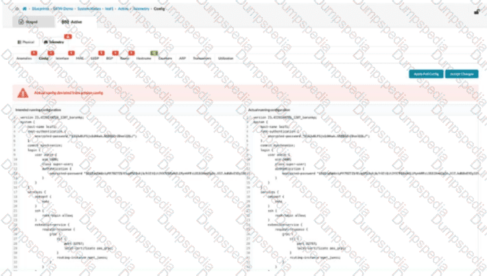
what happens when an operator clicks the Accept Changes button on the right side of the screen in Juniper Apstra?
Apstra will add a similar configuration from a known device context to accomplish the goal of the CLI-entered configuration.
Apstra will incorporate the new CLI into the “golden config”.
Apstra will not commit new changes to this device until the user clicks the Apply Full Config button.
Apstra will stop warning about the changes, but the changes will be overwritten at the next commit.
In Apstra 5.1, this screen represents a configuration deviation workflow: Apstra is comparing the intended (golden) configuration it generated from blueprint intent against the actual configuration currently on the device. When an operator makes a change directly on the switch CLI (for example, on a Junos v24.4 leaf), Apstra detects the difference and flags it as drift because it did not originate from the blueprint’s intent model.
Clicking Accept Changes tells Apstra to adopt the device’s current CLI state as the new accepted baseline for that device, effectively incorporating the observed CLI delta into Apstra’s intended configuration for purposes of future comparison and compliance. In other words, Apstra stops treating that specific deviation as an error because it has been acknowledged and absorbed into the “golden config” (the intent-aligned configuration Apstra considers correct for that node). This is commonly used when an emergency change was made on-box and you want Apstra’s source of truth to reflect it, rather than reverting it.
This differs from Apply Full Config, which is used to push Apstra’s intended configuration down to the device to restore compliance. If you do not accept the change, a later commit/apply action can overwrite the CLI-entered configuration to re-align with blueprint intent.
What are three valid resource types supported within Juniper Apstra? (Choose three.)
Integer pools
Routing zone pools
Interface pools
VNI pools
ASN pools
In Apstra 5.1, resources are values that must be allocated uniquely and consistently across a fabric so Apstra can render deterministic, conflict-free configurations. These values are managed through resource pools, which provide ranges (or sets) of assignable identifiers that Apstra can automatically allocate to blueprint elements during build and deployment.
Three valid resource pool types in Apstra are ASN pools, VNI pools, and integer pools. ASN pools supply Autonomous System Numbers used in IP fabric underlays (commonly eBGP in three-stage Clos), ensuring each device or role receives the correct AS assignment without manual tracking. VNI pools supply VXLAN Network Identifiers for overlay segmentation in EVPN-VXLAN fabrics. Apstra uses these to create scalable tenant segments where the VNI uniquely identifies the broadcast domain in the overlay, and Junos v24.4 devices (leaf VTEPs) are configured accordingly. Integer pools provide generic numeric values used mainly in Freeform-style designs or in situations where a template needs a consistent allocated integer (for example, a custom ID used by a configlet or another allocation-driven construct).
“Routing zone pools” and “interface pools” are not resource pool types in Apstra. Routing zones (VRFs) are blueprint design objects, and interfaces are physical/logical constructs, but neither is consumed as an allocatable “pool” resource type in the Apstra resource catalog model.
You staged several changes to your Juniper Apstra blueprint but have not committed them. In this scenario, what is the effect of selecting Revert?
All the staged changes are cleared.
Only the last staged change will be cleared.
The current active configuration will be replaced by the previous active configuration.
A commit is required to complete the revert operation.
In Apstra 5.1, blueprint changes follow an intent workflow: you edit intent in Staged, then review the delta in Uncommitted, and finally Commit to activate those changes and create a new revision. If you have staged changes that are visible under Uncommitted but decide not to proceed, the Revert action is used to discard them. Selecting Revert clears the blueprint’s uncommitted intent delta and returns the blueprint to the last committed state (the currently active intended design baseline). In practical terms, it removes all pending edits that were made since the last commit—whether those edits were physical (links/topology), virtual (routing zones, virtual networks), policies (security policies), or catalog-driven operations—so that none of those changes will be deployed.
Revert is not a “single-step undo” limited to only the most recent change; it is a discard of the staged/uncommitted change set. It also does not roll back device configurations on its own (that is handled by revision operations such as Time Voyager rollbacks and subsequent deployment actions). Finally, Revert does not require a commit to take effect; it is used specifically to avoid committing changes. This behavior helps maintain clean operational control in EVPN-VXLAN fabrics by ensuring only validated and intentional intent updates are promoted to the deployed network state.
Verified Juniper sources (URLs):
https://www.juniper.net/documentation/us/en/software/apstra4.2/apstra-user-guide/topics/task/blueprint-commit-revert.html
https://www.juniper.net/documentation/us/en/software/apstra6.1/apstra-user-guide/topics/task/time-voyager-rollback-blueprint-revision.html


TESTED 14 Oct 2026