dumpspedia logo

[Exhibit]
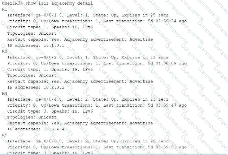
Click the Exhibit button.
Which two statements about the IS-IS output shown in the exhibit are correct? (Choose two.)
R3 is connected to the IS-IS backbone.
R3 is connected to two Level 1 IS-IS neighbors.
These IS-IS neighbors have the IPv6 address family disabled.
The IS-IS adjacency with R5 requires authentication.
This detailed adjacency output shows R3 maintaining four separate, fully Up adjacencies, evenly split between the two IS-IS levels. R1 and R2 are both formed at Level 1, confirming that R3 is directly adjacent to exactly two Level 1 neighbors within its local area, which validates that statement. R4 and R5 are both formed at Level 2, and Level 2 adjacencies are, by definition, part of the IS-IS backbone that interconnects areas; a router maintaining any Level 2 adjacency is by that fact participating in and connected to the Level 2 backbone, confirming R3's backbone connectivity as well. Every one of the four listed adjacencies explicitly shows 'Speaks: IP, IPv6' in its detail output, which is Junos's way of indicating that both the IPv4 and IPv6 address families have been successfully negotiated and are active over that circuit; this directly contradicts, rather than supports, the claim that IPv6 is disabled on these neighbors — if IPv6 were disabled, the Speaks field would list only IP. Regarding authentication, the output contains no field, flag, or indication whatsoever referencing authentication configuration or state for the R5 adjacency (or any adjacency); Junos would typically surface authentication-related information separately if it were configured and relevant, and its complete absence here means no basis exists in the exhibit to conclude authentication is required for that specific adjacency. Reference topics: Junos Enterprise Routing – IS-IS, Level 1 and Level 2 Adjacencies and Address Family Negotiation.
You have configured a GRE tunnel from your local router with tunnel source 10.0.0.1 to a remote router at destination 192.168.0.1. The tunnel is functioning until you commit set routing-options static route 0.0.0.0/0 next-hop gr-0/0/0. This configuration causes the tunnel to go down.
Which statement is correct in this scenario?
A GRE interface cannot be used as a next hop for a static route.
The destination IP was being resolved using the default route, which now points to the tunnel itself.
A GRE interface must use the loopback as its source address to be used as a default route.
The tunnel destination must be resolved by a /32 host route.
A GRE tunnel's outer, delivery-layer packets are forwarded using the router's ordinary underlay routing table, meaning the tunnel destination address (192.168.0.1 in this case) must itself be resolvable to a physical, non-tunnel next hop for the encapsulated packets to actually leave the router. Before this configuration change, the default route (or some more specific route) presumably pointed toward a real physical next hop, allowing the router to reach 192.168.0.1 and keep the tunnel operational. When the administrator commits a static default route of 0.0.0.0/0 with a next hop of gr-0/0/0, every destination lookup that previously fell back to the default route — including the lookup for the tunnel's own destination address, 192.168.0.1, since no more specific route exists for it — now recurses through the GRE interface itself. This creates a circular dependency: the router needs to route to 192.168.0.1 to keep the tunnel up, but the only route it has to reach 192.168.0.1 now points back into the tunnel that requires 192.168.0.1 to already be reachable, so the interface's next-hop resolution fails and the tunnel drops. This is an entirely valid and common GRE design pitfall rather than any platform restriction; GRE interfaces can be legitimately used as static route next hops, do not require loopback-sourced encapsulation, and do not require a /32 host route to resolve their destination, provided that route does not recursively point back through the tunnel. Reference topics: Junos Enterprise Routing – Tunneling, Route Recursion and GRE Tunnel Destination Resolution.
You are creating an aggregated Ethernet bundle using LACP on your Juniper Networks EX Series device.
In this scenario, which statement is correct?
LACP active mode is required on at least one side of the bundle.
You must use different LACP system priorities for each switch.
By default, LACP is in active mode on aggregated Ethernet interfaces.
LACP active mode is required on both sides of the bundle.
IEEE 802.3ad LACP defines two distinct negotiation modes, active and passive, and the standard's fundamental requirement for successful negotiation is that at least one end of the point-to-point link must be configured in active mode; an actively configured device initiates LACPDU transmission on its own, while a passively configured device waits and only responds once it receives an LACPDU from its peer. If both ends of the bundle were left in passive mode simultaneously, neither side would ever initiate the exchange, and no negotiation — and therefore no functioning aggregated bundle — would ever occur; at least one active participant is therefore mandatory, though having both sides active (active-active) is also fully valid and is in fact the most common production deployment. Junos does not enable LACP automatically on aggregated Ethernet interfaces; unlike some competing platforms, LACP must be explicitly configured under the aggregated-ether-options lacp hierarchy, and specifying no LACP configuration at all results in a 'static' LAG that relies purely on physical link-state rather than any protocol negotiation — there is no implicit default active mode. There is likewise no requirement to configure differing LACP system priority values between the two peer switches; system priority is used only to determine which side of the link controls port selection during negotiation and has no bearing on whether the bundle can form. Both sides being mandatorily active is a stricter requirement than the actual standard specifies. Reference topics: Junos Enterprise Switching – Link Aggregation, LACP Active and Passive Mode Negotiation.
What are two characteristics of IS-IS? (Choose two.)
IS-IS is an interior gateway protocol.
IS-IS L1 routers route traffic between areas.
IS-IS routes use a default preference of 20.
IS-IS L1/L2 routers route traffic between areas.
IS-IS (Intermediate System to Intermediate System) was designed by ISO as a link-state Interior Gateway Protocol for routing within a single autonomous system, functioning on a hierarchical two-level model conceptually similar to OSPF's areas, which makes the first statement unambiguously correct. Within that hierarchy, Level 1 routers maintain detailed topology information only for their own local area and use a default route toward the nearest Level 2 or Level 1/Level 2 router to reach destinations outside the area; they explicitly do not carry inter-area topology information and therefore cannot route traffic between areas on their own. Routers that participate in both levels simultaneously — Level 1/Level 2 (L1/L2) routers — sit at the area boundary, maintaining a Level 1 database for their local area and a Level 2 database for the backbone, and it is specifically these dual-level routers that stitch inter-area traffic together, forwarding packets from the local area into the Level 2 backbone and vice versa, which confirms the second correct statement. Regarding route preference, Junos assigns distinct default preference (administrative distance) values of 15 for IS-IS Level 1 routes and 18 for IS-IS Level 2 routes — neither of which is 20 — so the preference-value statement is factually incorrect and included as a distractor testing precise knowledge of Junos default protocol preferences. Reference topics: Junos Enterprise Routing – IS-IS, Level 1, Level 2, and L1/L2 Router Roles; Default Route Preference Values.
Which two fields must match in an OSPF hello packet to form an adjacency over a broadcast link? (Choose two.)
network mask
designated router
router priority
dead interval
RFC 2328 specifies a precise set of parameters that two OSPF routers on a broadcast network must agree upon before a valid neighbor relationship can be established, and a mismatch in any of these mandatory fields causes the routers to reject each other's Hello packets outright rather than forming even a basic 2-Way state. The network mask carried in each Hello packet must match between neighbors on a broadcast segment, since OSPF uses this field to confirm both routers agree on the subnet boundaries of the shared segment; a mismatched mask (for example, one router configured with a /24 and its neighbor with a /25 on the same physical wire) is treated as a configuration error and blocks adjacency formation. The router dead interval, which defines how long a router will wait without receiving a Hello before declaring a neighbor down, must likewise match exactly between neighbors, alongside the closely related hello interval, since these timers govern the shared expectations both sides have for how frequently Hellos should arrive and how quickly a failure should be detected; Junos explicitly checks and rejects Hello packets carrying a mismatched dead interval value. Router priority, by contrast, is intentionally allowed to differ between neighbors on the same segment — it exists precisely so that administrators can differentiate router preference for the DR/BDR election, and differing values are expected and normal rather than being blocked. The designated router field, as advertised within each Hello, is informational about the sender's current view of the segment's DR and is not a value that must be identical between the two Hello senders to permit adjacency formation. Reference topics: Junos Enterprise Routing – OSPF, Required Hello Parameter Matching on Broadcast Networks.
Which statement describes how nonstop active routing (NSR) maintains routing protocol information during a Routing Engine switchover?
The backup Routing Engine retrieves routing information from neighboring routers after a switchover.
The primary Routing Engine copies protocol information only when an NSR event begins.
The backup Routing Engine continuously synchronized protocol states by running the RPD process.
The Packet Forwarding Engine updates protocol state based on the most recent LSA or BGP update received.
Nonstop active routing's defining architectural feature is that the backup Routing Engine runs a fully live, active instance of the routing protocol daemon (rpd) in parallel with the primary Routing Engine's rpd instance, continuously, from the moment NSR and its prerequisite GRES are established — not merely at the instant a switchover begins. As protocol adjacencies form, routes are learned, and the RIB is updated on the primary Routing Engine, that same protocol and RIB state is mirrored in real time to the backup Routing Engine's rpd process through an internal synchronization mechanism, so the backup's protocol state remains a live, up-to-date replica of the primary's at essentially every moment during normal operation. When a switchover occurs, the backup Routing Engine simply assumes the primary role with protocol adjacencies, routing tables, and forwarding state already fully populated and current, allowing it to continue operating without re-establishing neighbor relationships or re-learning the network topology, which is what makes the switchover genuinely nonstop and invisible to neighboring routers. This is fundamentally different from graceful restart, where the restarting router must rebuild its state by requesting help from cooperating neighbors after the fact. The Packet Forwarding Engine plays no role in synchronizing protocol-layer information such as LSAs or BGP updates; that is strictly an rpd-to-rpd function coordinated through the Routing Engine synchronization infrastructure. Reference topics: Junos Enterprise Routing – High Availability, Nonstop Active Routing Architecture and rpd Synchronization.
How would you view the metric assigned to a route in OSPF? (Choose two.)
Use the show route protocol ospf command.
Use the show ospf route intra command.
Use the show ospf database extensive command.
Use the show ospf interface command.
The metric that OSPF assigns to a destination is visible from two complementary vantage points in Junos. The show route protocol ospf command displays the main routing table filtered to OSPF-learned prefixes, and each entry shows the computed cost alongside the next hop, exactly as it was installed after SPF calculation. The show ospf route command (which accepts filters such as intra-area, inter-area, and extern) presents the OSPF-specific routing table, organized by route type, and explicitly lists the metric column for every intra-area, inter-area, and external route the local router has calculated. Together these two commands give both the RIB-level and the protocol-level view of route cost. By contrast, show ospf database extensive dumps the raw link-state advertisements, where metrics appear only as link-level values buried inside Router or Network LSAs rather than as a resolved route cost, so it is not the direct tool for viewing a route's metric. show ospf interface reports interface operational state, area, and DR/BDR information but does not present a cost or metric field at all in its standard output. Candidates should be comfortable distinguishing the RIB-oriented and protocol-table-oriented verification commands, since JNCIS-ENT scenarios frequently test whether a candidate reaches for the correct show command layer during troubleshooting. Reference topics: Junos Enterprise Routing – OSPF Operation and Verification, Monitoring OSPF.
You enable the point-to-point parameter on your OSPF interface configuration.
In this scenario, what are two benefits of this action? (Choose two.)
It enables OSPF adjacencies to establish quicker.
It enables the advertisement of a connected OSPF network.
It enables an OSPF router to win the designated router election on a broadcast link.
It reduces the size of the OSPF link-state database.
Configuring interface-type p2p under an OSPF interface tells Junos to treat that interface as a point-to-point network type regardless of the underlying physical medium, which removes the interface from the standard broadcast-network state machine entirely. On a true broadcast network, two routers must first complete a Designated Router and Backup Designated Router election, wait through the associated timers, and only then proceed through 2-Way, ExStart, Exchange, and Loading before reaching Full — a multi-step process. A point-to-point interface skips DR/BDR election altogether and proceeds directly from 2-Way into ExStart, so adjacencies form measurably faster, which is the first correct benefit. Because there is no DR on a point-to-point interface, Junos also does not generate a Type 2 Network LSA to describe the segment; the connected subnet is instead advertised as a simple stub-network entry inside the Router LSA itself, eliminating an entire LSA type from the area's link-state database and reducing its overall size, which is the second correct benefit. Point-to-point configuration is entirely incompatible with DR election, so a router configured this way cannot 'win' a DR election — there is no DR to win. Advertisement of the connected network happens on any operational OSPF interface irrespective of network type, so that option describes normal OSPF behavior rather than a benefit specific to the point-to-point setting. Reference topics: Junos Enterprise Routing – OSPF Network Types, Configuring OSPF Interface Type.
[Exhibit]
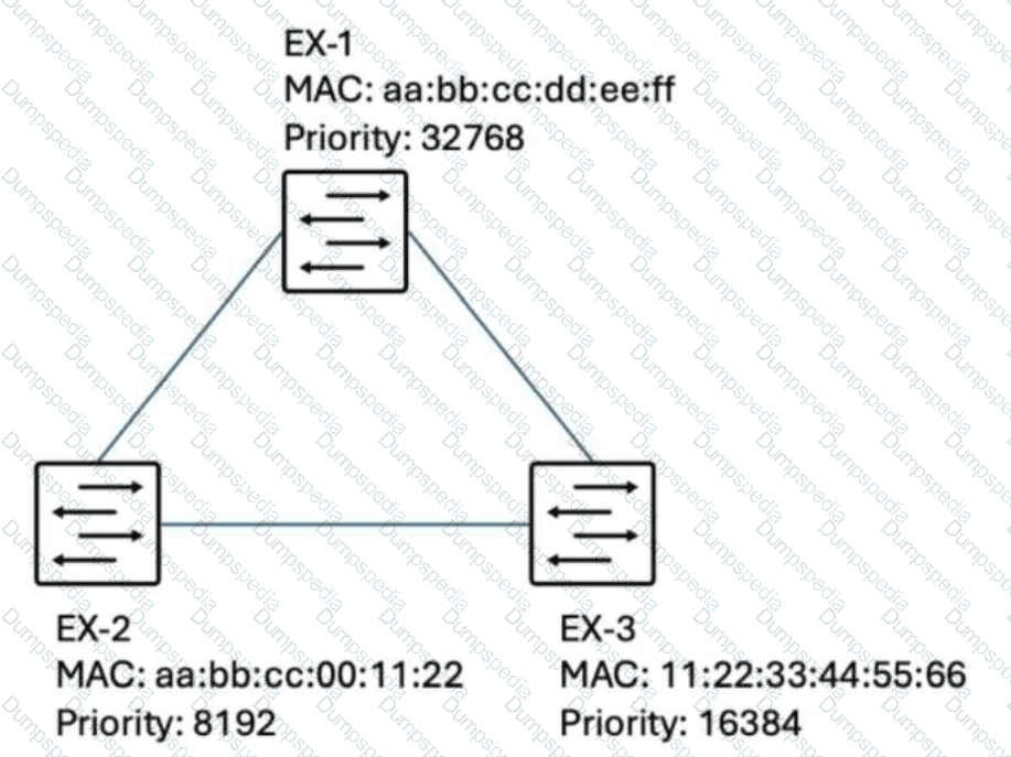
Click the Exhibit button.
You have three Juniper Networks EX Series Switches in an STP domain as shown in the exhibit.
Which statement describes the switch that will be elected as the root bridge?
EX-2, because its MAC address is the lowest.
EX-1, because its MAC address is the highest.
EX-1, because its priority is the highest.
EX-2, because its priority is the lowest.
Root bridge election in Spanning Tree Protocol is governed entirely by the Bridge Identifier, an 8-byte value formed by concatenating the configured bridge priority (the higher-order, more significant portion of the comparison) with the switch's MAC address (used strictly as a tiebreaker when priorities are identical). Every participating switch compares Bridge IDs, and the switch advertising the numerically lowest Bridge ID is elected root. In this exhibit, the three switches have distinctly different priority values — EX-1 at the Junos/IEEE default of 32768, EX-2 at 8192, and EX-3 at 16384 — meaning the comparison is decided entirely at the priority stage and never needs to proceed to a MAC address tiebreak at all. Since 8192 is numerically the lowest of the three priority values, EX-2 is elected root bridge purely on the strength of its lower priority, regardless of what its MAC address happens to be. This is precisely why the correct answer cites priority rather than MAC address as the deciding factor: MAC address only becomes relevant as a tiebreaker in the specific case where two or more switches share an identical priority value, which is not the situation presented here. Understanding that priority is evaluated first and is independently sufficient to decide the outcome whenever it differs is a foundational and heavily tested Spanning Tree concept on the JNCIS-ENT exam. Reference topics: Junos Enterprise Switching – Spanning Tree Protocols, Bridge ID and Root Bridge Election.
You need to block SSH (TCP port 22) traffic from the 192.168.10.0/24 network.
Which firewall filter term is correct in this scenario?
term block-ssh { from { source-address 192.168.10.0/24; protocol tcp; destination-port 22; } then discard; }
term block-ssh { from { destination-address 192.168.10.0/24; protocol tcp; destination-port 22; } then discard; }
term block-ssh { from { source-address 192.168.10.0/24; protocol tcp; source-port 22; } then discard; }
term block-ssh { from { source-address 192.168.10.0/24; service ssh; } then reject; }
Correctly blocking SSH traffic originating from a specific network requires matching three precise conditions simultaneously in the from clause: the traffic's source-address must equal the 192.168.10.0/24 network, since the requirement is to block traffic coming from that network rather than traffic destined to it; the protocol must be explicitly set to tcp, since SSH operates exclusively over TCP; and the destination-port must be set to 22, because an inbound SSH connection request is always directed at the well-known SSH listening port 22 on the receiving side, regardless of which ephemeral source port the initiating client happens to use. The first option satisfies all three conditions correctly and pairs them with a discard action, cleanly dropping matching traffic. The second option incorrectly substitutes destination-address for source-address, which would match traffic heading toward that /24 rather than traffic originating from it, inverting the intended match direction. The third option incorrectly uses source-port 22 instead of destination-port 22; since the SSH client's source port is a randomly assigned ephemeral value rather than a fixed 22, this term would almost never match real SSH session-initiation traffic. The fourth option relies on a service ssh match condition, which is not valid syntax within the standard Junos firewall filter grammar for family inet; there is no such application-based keyword available at that hierarchy, making the term invalid regardless of the reject action chosen. Reference topics: Junos Enterprise Switching – Firewall Filters, Matching on Address, Protocol, and Port Conditions.
You have traffic for a video streaming application traversing a GRE tunnel in your network and users are reporting poor performance. Both ends of the tunnel are using the default settings for a gigabit Ethernet interface, but you observe excessive packet drops due to exceeding the MTU.
Which two steps would you take to improve connectivity for this application? (Choose two.)
Increase the MTU for the member interfaces to 1524 bytes.
Route the GRE tunnel through a higher bandwidth link.
Configure the clear-dont-fragment option on the member interfaces.
Increase the MTU for the member interfaces to 1500 bytes.
The described symptom — excessive packet drops specifically attributed to exceeding the MTU on a GRE tunnel carrying full-size video streaming traffic across default-MTU gigabit Ethernet interfaces — is a direct consequence of the 24 bytes of GRE encapsulation overhead pushing packets that were already at or near the standard 1500-byte Ethernet MTU past the physical interface's transmission limit once the outer GRE and IP headers are added. The most durable fix is to proactively increase the physical member interfaces' MTU beyond the 1500-byte default — to 1524 bytes or higher — which provides sufficient headroom to absorb the full GRE encapsulation overhead without ever causing the fully encapsulated packet to exceed the interface's transmission capability, allowing full-size 1500-byte payloads to pass through the tunnel intact and without fragmentation or drops. As a complementary measure, configuring the clear-dont-fragment-bit option on the tunnel or member interfaces instructs Junos to clear the DF (don't fragment) bit on oversized packets rather than dropping them outright when they do exceed the available MTU, allowing the Packet Forwarding Engine to fragment and later reassemble the traffic instead of silently discarding it, which directly addresses the reported packet loss even under transient conditions. Simply raising the MTU only to 1500 bytes fails to account for the 24-byte GRE overhead and would not resolve the underlying oversize condition. Routing the tunnel over a higher-bandwidth link addresses potential congestion but does nothing to correct an MTU-based packet-size violation, which is the root cause explicitly identified in this scenario. Reference topics: Junos Enterprise Routing – Tunneling, GRE MTU Sizing and Fragmentation Handling for High-Throughput Applications.
A GRE tunnel is experiencing fragmentation issues. You confirm that the tunnel is up and is functioning correctly. You confirm that hosts are sending 1500-byte packets.
In this scenario, which statement is correct?
You should use the clear-dont-fragment parameter to allow fragmentation.
You should lower the physical interface's MTU to 1476 bytes to avoid fragmentation.
You should enable BFD to more rapidly identify tunnel link failures.
You should use ToS copying to reduce header size.
GRE encapsulation adds a fixed 24 bytes of overhead to every packet it carries — 4 bytes for the GRE header itself and 20 bytes for the new outer IPv4 delivery header. When a host transmits a full 1500-byte Ethernet payload into a gr- interface, the resulting encapsulated packet becomes 1524 bytes, which exceeds the physical interface's standard 1500-byte MTU and forces fragmentation or drops if the don't-fragment bit is set. The correct remediation is to reduce the effective MTU seen by end hosts so that encapsulated packets never exceed the physical link's transmission limit. Junos automatically applies this logic to gr- logical interfaces, which default to a 1476-byte protocol MTU (1500 minus 24), but when the underlying physical interface or a manually configured path is involved, administrators must explicitly size the interface MTU to 1476 bytes to prevent post-encapsulation oversize packets. Allowing fragmentation with clear-dont-fragment is a workaround that increases CPU load and can degrade performance rather than solving the root cause, BFD addresses link-failure detection rather than MTU sizing, and ToS copying affects only the type-of-service byte, not packet length. Reference topics: Junos Enterprise Routing – Tunneling, GRE Encapsulation and MTU Considerations; Junos OS Configuring GRE Tunnel Interfaces.
Your company has a branch location that uses a Juniper Networks EX Series Switch. You are asked to troubleshoot a spanning-tree issue that keeps reoccurring within the branch environment. After investigation, you discover that end-devices running a virtualization application are generating BPDUs, which are disrupting the spanning-tree topology and causing periodic outages.
Which solution will prevent this problem from reoccurring?
Increase the max-age timer on all EX Series Switches.
Disable RSTP on all access interfaces.
Configure BPDU protection on all edge interfaces.
Configure root protection on all access interfaces.
This scenario describes end hosts — virtualization hosts running software switches or virtual bridging stacks — unexpectedly generating and transmitting BPDUs on ports that are supposed to be pure edge (host-facing) ports where no BPDUs should ever legitimately be received. BPDU protection (BPDU guard) is the Junos feature purpose-built for exactly this situation: when applied to an edge-designated interface, it continuously monitors that port for any incoming BPDU, and the moment one is detected, it immediately and automatically disables the port, preventing the unexpected BPDU source from ever participating in or influencing the spanning-tree topology calculation, thereby protecting the stable, intended topology from disruption caused by unauthorized or accidental BPDU generation at the access edge. This directly and precisely resolves the described problem at its source, since the root cause is illegitimate BPDUs arriving on ports that were never meant to see them. Increasing the max-age timer only adjusts how long stale topology information is retained before being aged out and has no effect on preventing rogue BPDUs from being processed in the first place. Disabling RSTP outright on access interfaces would eliminate spanning tree's loop-prevention protection on those ports entirely, introducing a much more severe risk of undetected Layer 2 loops. Root protection (root guard) defends specifically against a port attempting to become the root port by receiving a superior BPDU claiming a better path to root; it addresses a different threat model than blocking any BPDU outright on a true edge port. Reference topics: Junos Enterprise Switching – Spanning Tree Protocols, BPDU Protection on Edge Interfaces.
[Exhibit]
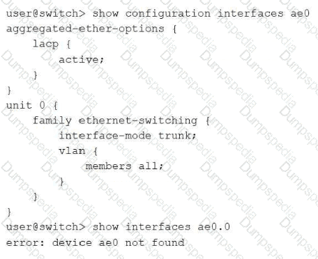
Click the Exhibit button.
You are troubleshooting an aggregated Ethernet interface on a Juniper Networks EX Series Switch. The aggregated Ethernet interface does not appear in the output shown in the exhibit.
Which action will solve this problem?
Configure the number of aggregated Ethernet devices under the [edit chassis] hierarchy.
Install the aggregated Ethernet interface license on the switch.
Restart the switch to enable the aggregated Ethernet switching process.
Configure LACP passive-mode.
On EX Series switches, aggregated Ethernet (ae) interfaces do not exist by default; before any ae interface can be created, referenced, or brought into service, an administrator must first reserve the desired number of aggregated Ethernet device slots by configuring set chassis aggregated-devices ethernet device-count number at the [edit chassis] hierarchy. This statement allocates the internal resources needed for that many ae interfaces to exist as valid, configurable objects; until it is committed, any interface-level configuration referencing ae0 (such as the aggregated-ether-options and family ethernet-switching stanzas shown in the exhibit) is accepted syntactically by the CLI but never actually instantiates a live ae0 device, which is exactly why show interfaces ae0.0 returns 'device ae0 not found' despite the interface appearing fully configured. Increasing the device-count to at least 1 (or higher, to cover the number of LAG bundles planned) immediately resolves this and allows ae0 to appear as an operational interface once its member links are also associated with it. This is a foundational and frequently overlooked prerequisite step in LAG deployment on Juniper switches. There is no separate licensing requirement for aggregated Ethernet functionality on EX Series switches, a reboot is not needed since the chassis statement takes effect upon commit, and the LACP mode (active versus passive) is unrelated to whether the ae interface object itself exists in the first place. Reference topics: Junos Enterprise Switching – Link Aggregation, Configuring the Aggregated Ethernet Device Count.
Which IS-IS PDU should be used by a router to list all LSPs that it believes should exist in the link-state database?
CSNP
PSNP
LSP
IIH
The Complete Sequence Number PDU (CSNP) is the IS-IS mechanism used to summarize the entire contents of a router's link-state database, listing the LSP ID, sequence number, checksum, and remaining lifetime for every LSP the sending router currently believes should exist in the database for that level. On broadcast (LAN) circuits, the elected Designated Intermediate System periodically transmits CSNPs to all routers on the segment as a database-synchronization mechanism; any receiving router compares the summarized list against its own local database, and any discrepancy — an LSP it is missing entirely, or one for which it holds an older sequence number — triggers a targeted request for the specific, updated LSP content. On point-to-point circuits, a single CSNP is exchanged once when the adjacency first comes up, serving the identical synchronization purpose without needing periodic repetition. The Partial Sequence Number PDU (PSNP), by contrast, is used to acknowledge receipt of specific LSPs or to explicitly request specific LSPs identified as missing or outdated after a CSNP comparison, making it a partial, targeted PDU rather than a complete database listing. The LSP itself is the PDU that actually carries the detailed topology and reachability information being advertised, rather than a database summary. The IS-IS Hello PDU (IIH) is used purely for neighbor discovery and adjacency maintenance and carries no link-state database summary information whatsoever. Reference topics: Junos Enterprise Routing – IS-IS, CSNP and Link-State Database Synchronization.
On Juniper devices, which statement correctly describes a basic characteristic of a GRE tunnel?
GRE tunnels support only IPv4 payload encapsulation.
GRE tunnels need keepalives configured by default to stay operational.
GRE tunnels require the tunnel endpoints to have a valid route to each other.
GRE tunnels maintain session state information about the remote endpoint.
GRE is fundamentally a stateless encapsulation protocol: the encapsulating router simply wraps the passenger packet in a GRE header and an outer delivery IP header and forwards it based on ordinary IP routing table lookups toward the configured tunnel destination address. For that forwarding to succeed, the underlying (global or routing-instance) routing table on each endpoint must contain a valid, reachable route to the far-end tunnel address; without such a route, the tunnel interface will not come up or will be unable to deliver traffic, since GRE relies entirely on the existing IP infrastructure rather than any tunnel-specific signaling to establish reachability. Because GRE has no built-in state machine or session negotiation, it does not natively track whether the remote endpoint is alive — that requires an optional add-on such as GRE keepalives or BFD, neither of which is enabled by default; an operator must explicitly configure them if failure detection is required. GRE is also protocol-agnostic rather than IPv4-only: it can encapsulate IPv4, IPv6, MPLS, and other network-layer protocols as the passenger, which is one of its defining advantages over IP-in-IP tunneling. Finally, because GRE keeps no per-session state about the peer, it cannot detect or report tunnel failures on its own, reinforcing why route reachability is the one true prerequisite for tunnel operation. Reference topics: Junos Enterprise Routing – Tunneling, Understanding Generic Routing Encapsulation.


TESTED 23 Sep 2026