You are using EBGP to connect to two upstream peers in the same AS. You want to make one of the links less preferred for traffic entering your network from the peer's AS. Which feature should you use to achieve this goal?
a route reflector
origin code
AS-path prepending
local preference
In the world of BGP, controllinginbound traffic(traffic entering your network) is significantly more challenging than controlling outbound traffic because it requires influencing a decision made by an external Autonomous System (AS). According to Juniper Networks documentation, when you have multiple links to the same AS or even different ASes, the BGP path selection process is used by the upstream neighbor to decide which path to take to reach your prefixes.
AS-Path Prependingis the standard technique used to make a path appear less attractive to external peers. By artificially lengthening the AS_PATH attribute on the BGP advertisements sent over a specific link, you exploit the BGP best-path algorithm rule that prefers a shorter AS path. When you prepend your own AS number multiple times to the update sent to the "less preferred" peer, that peer’s BGP routers will see a longer path compared to the alternative link and will naturally prefer the shorter, unprepended route.
It is important to distinguish why other options are incorrect for this specific goal:
Local Preference (Option D):This is a well-known discretionary attribute used to influenceoutboundtraffic. It is not advertised to EBGP peers; therefore, your upstream neighbor cannot see your local preference settings.
Origin Code (Option B):While the origin code (IGP, EGP, or Incomplete) is a tie-breaker in the selection process, it is rarely used for traffic engineering and lacks the granular control provided by prepending.
Route Reflector (Option A):This is an Internal BGP (IBGP) scaling mechanism used to reduce the need for a full mesh of peers within an AS; it does not directly influence external path selection by an upstream provider.
Junos OS allows you to easily implement prepending viarouting policiesapplied as an "export" policy to the EBGP neighbor. By using the as-path-prepend action within a policy term, you can selectively degrade a path's attractiveness to manage your inbound bandwidth.
Which two statements regarding GRE and IP-IP tunnels are correct? (Choose two.)
These tunnels add additional overhead to the packets that traverse them.
These tunnels do not add any overhead to the packets that traverse them.
These tunnels offer secure encryption mechanisms.
These tunnels do not offer encryption mechanisms.
In Juniper Networks Junos OS,Generic Routing Encapsulation (GRE)andIP-in-IP (IP-IP)are common tunneling mechanisms used to transport packets across a network by encapsulating them within another protocol. Understanding the header structure and the limitations of these protocols is essential for proper MTU (Maximum Transmission Unit) management and security design.
Overhead (Option A):
Both GRE and IP-IP tunnels operate by adding an additional IP header to the original packet. An IP-IP tunnel (Protocol 4) adds a20-byteIPv4 header. A GRE tunnel (Protocol 47) adds the same20-bytedelivery IP header plus a minimum4-byteGRE header (totaling 24 bytes, which can increase if keys or sequencing are used). Because these headers are added to the payload, the total size of the packet increases. This "overhead" means that if the original packet was already at the MTU limit (e.g., 1500 bytes), the encapsulated packet will exceed it, potentially leading to fragmentation or the need to adjust theTCP MSS (Maximum Segment Size).
Encryption (Option D):
Crucially, according to Juniper Service Provider documentation, neither GRE nor IP-IP provides nativeencryptionor data confidentiality. They are encapsulation protocols, not security protocols. The payload remains in cleartext and is visible to any device along the path. If security and encryption are required for data traversing these tunnels, they must be combined withIPsec (IP Security). While GRE is often used as the "carrier" for IPsec (to allow multicast or dynamic routing protocols which IPsec alone does not support), the GRE protocol itself remains an unencrypted delivery mechanism. Therefore, statements A and D accurately describe the architectural behavior of these tunnel types.
What information is determined by using the AS path attribute included in the BGP update message? (Choose two.)
the origin of a route from IGP or EGP
the presence of a routing loop
the shortest AS path to reach a prefix
the total number of next-hop devices to reach a prefix
TheAS_PATHattribute is a "well-known mandatory" attribute in BGP, meaning it must be present in every BGP Update message exchanged between External BGP (eBGP) peers. It records the sequence of Autonomous System numbers that a route has traversed. Per Juniper Networks Service Provider documentation, this attribute serves two fundamental purposes:
1. Loop Prevention (Option B):
This is the most critical function of the AS_PATH. When a BGP router receives an update from an eBGP peer, it scans the AS_PATH attribute for its own AS number. If the router finds its local AS number already listed in the path, it concludes that the route has already passed through its network and has "looped" back. To prevent an infinite routing loop, the router will immediately discard the update. This mechanism is the cornerstone of BGP's stability as a path-vector protocol.
2. Path Selection / Shortest Path Determination (Option C):
BGP uses a complex "tie-breaking" algorithm to select the best path among multiple candidates. One of the highest-ranking criteria in this algorithm (after Weight, Local Preference, and AS_PATH length) is the length of the AS_PATH. A shorter AS_PATH (fewer AS numbers listed) is generally preferred over a longer one, as it typically represents a more direct path through the internet hierarchy.
Why other options are incorrect:
Option A:The "origin" of a route (IGP, EGP, or Incomplete) is determined by theORIGINattribute, which is a separate well-known mandatory attribute.
Option D:BGP does not count individual "next-hop devices" (which would be an IGP metric like hop count in RIP); it only tracks Autonomous Systems. A single AS in the path might contain hundreds of internal routers (next-hops), but BGP only sees it as one "hop" in the AS_PATH.
You are configuring BGP on a Juniper router to peer with an external provider. After committing the configuration, the BGP session remains in the Idle state. Which configuration issue would prevent the BGP session from progressing beyond the Idle state?
The peer IP address is unreachable.
The local AS number is higher than the peer’s AS number.
The peer is configured with a different router ID.
The BGP group type is set to internal instead of external.
In the BGP finite state machine, theIdlestate is the "stop" or "start" point of the protocol. When a session is stuck in Idle, it means the BGP process is either administratively disabled or, more commonly, is unable to initiate the underlying TCP connection required for BGP.
According to Juniper Networks Service Provider documentation, the most common reason for a BGP session to remain in Idle is a lack ofrouting reachability. For BGP to move to theConnectstate, the Junos kernel must have a route to the IP address specified in the neighbor statement. If thepeer IP address is unreachable (Option A)—meaning there is no route in inet.0 (via OSPF, IS-IS, or static)—the router cannot initiate the TCP three-way handshake on port 179. Consequently, the state machine will never progress.
Analysis of incorrect options:
Option B:BGP does not care if the local AS is higher or lower than the peer's; it only cares if they match the configuration. AS numbers are identifiers, not priorities.
Option C:A mismatchedRouter IDdoes not prevent a session from leaving the Idle state. It would typically cause the session to reach theOpenConfirmstate, and then fail with a "Notification" message due to a collision or identification error.
Option D:While a mismatchedgroup type(internal vs. external) will cause the session to fail, it usually fails during theOpenmessage exchange (OpenSent state) because the AS numbers provided will not match the expected peer type (IBGP vs. EBGP).
Only the lack of a path to the neighbor (reachability) keeps the session at the very beginning of the process: theIdlestate.
You are monitoring OSPF on a router and notice frequent state changes between Full and Down. Which condition would cause this behavior?
physical interface flapping
route preference mismatch
area ID mismatch
MTU mismatch
When troubleshooting OSPF in a service provider environment, distinguishing between "stuck" adjacencies and "flapping" adjacencies is the first step. A session that transitions frequently betweenFullandDownindicates that the relationship can be established successfully (meaning parameters match), but it cannot be maintained.
According to Juniper Networks documentation, the most common cause for a session to drop from Full to Down is the expiration of theDead Interval. If a router does not receive a Hello packet within the Dead Interval (usually 40 seconds), it tears down the adjacency. Aphysical interface flapping (Option A)is the primary trigger for this. If the physical link or the underlying transport (like a leased line or a microwave link) goes down even momentarily, the OSPF process immediately detects the interface failure, flushes the neighbors, and moves the state to Down. As soon as the interface comes back up, the routers perform the Hello exchange and reach the Full state again, creating the flapping cycle.
Analysis of other options:
MTU Mismatch (Option D):This typically causes the adjacency to get "stuck" in theExchangeorExStartstate. The routers can exchange small Hello packets, but when they try to send larger Database Description (DBD) packets that exceed the MTU, the packets are dropped, preventing the session from ever reaching "Full."
Area ID Mismatch (Option C):This prevents the adjacency from even reaching theInitstate; the routers will never form a neighbor relationship.
Route Preference (Option B):This affects which route is chosen for the forwarding table but has no impact on the OSPF neighbor state machine itself.
You are troubleshooting a Level 1 IS-IS router that has an adjacency with a Level 1/2 router. Which two statements are correct in this scenario? (Choose two.)
The Level 1/2 router merges Level 1 and Level 2 into one complete topology.
The Level 1 router will learn the full topology of the Level 2 network.
The Level 1/2 router sees the Level 1 network and the Level 2 network as two separate topologies.
The Level 1 router will only learn the topology of the Level 1 network.
In the context ofJuniper Networks Junos OSand theIS-IS (Intermediate System to Intermediate System)protocol, understanding the hierarchical relationship between router levels is critical for effective troubleshooting and design. IS-IS uses a two-level hierarchy to manage scalability:Level 1 (L1), which represents intra-area routing, andLevel 2 (L2), which represents inter-area backbone routing.
When a router is configured as aLevel 1/2 (L1/L2)device, it acts as a bridge between the two levels. According to Juniper technical documentation, an L1/L2 router maintains two completelyseparate Link-State Databases (LSDB)—one for Level 1 and one for Level 2. It does not merge these into a single topology. This separation ensures that local area topology changes (L1) do not necessarily flood into the backbone (L2) unless specific redistribution is configured, and vice versa. Therefore, statementCis correct because the L1/L2 router maintains distinct SPF (Shortest Path First) computations for each level.
Regarding the visibility of the Level 1 router, IS-IS is designed to keep L1 areas "stubby" by default. ALevel 1 routeronly possesses the topology information for its own area (the Level 1 LSDB). It does not receive specific L2 routes or the L2 topology. Instead, the L1/L2 router sets theAttached (ATT) bitin its L1 Link-State PDUs (LSPs) to signal to L1-only routers that it has a connection to the backbone. The L1 router then generates a default route pointing to the L1/L2 router to reach inter-area destinations. This confirms that statementDis correct: the L1 router's knowledge is limited to its local L1 topology.
Conversely, statements A and B are incorrect because merging topologies would violate the hierarchical scaling principles of IS-IS, and L1 routers never learn the full L2 topology without explicit, non-standard route leaking.
How are routing loops prevented in internal BGP networks?
Internal BGP routes are never readvertised to other internal BGP neighbors.
External BGP routes are never readvertised to other external BGP neighbors.
External BGP routes are never readvertised to other internal BGP neighbors.
Internal BGP routes are never readvertised to other external BGP neighbors.
The prevention of routing loops within an Autonomous System (AS) is handled differently than loop prevention between ASes. While External BGP (EBGP) uses the AS_PATH attribute to detect loops,Internal BGP (IBGP)does not modify the AS_PATH. Therefore, a different mechanism is required to ensure that a route does not circulate infinitely inside the network.
This mechanism is known as theIBGP Split Horizon rule. According to Juniper Networks documentation and the BGP standard (RFC 4271), a BGP speakermust not advertise a route learned via an IBGP peer to any other IBGP peer. In simpler terms, "what is learned internally, stays local." This rule ensures that a route only travels one "hop" inside the AS—from the router that learned it from an external source to all other internal routers.
Because of this rule, IBGP routers do not naturally propagate routes through each other. This creates a requirement for afull meshof IBGP sessions, where every BGP-speaking router in the AS must have a direct peering session with every other BGP-speaking router. To mitigate the scaling issues of a full mesh in large service provider networks, architects useRoute ReflectorsorConfederations, which are authorized exceptions to the Split Horizon rule.
Option B is incorrect because EBGP peersdoadvertise EBGP routes to other EBGP peers (this is how the internet works). Option C is incorrect because EBGP-learned routesmustbe sent to IBGP peers so the internal network knows how to reach the outside world. Option D is incorrect because internal routesmustbe sent to external peers to advertise your network to the internet.
Which OSPF packet type is used to initiate and maintain neighbor relationships?
Hello
Database Description
Link-State Update
Link-State Acknowledgment
TheHello packetis the most basic, yet most vital, component of the OSPF protocol. It serves as the primary mechanism for neighbor discovery, parameter negotiation, and "keepalive" functionality. Per Juniper Networks' routing documentation, OSPF routers use the Hello protocol to dynamically discover other OSPF-enabled routers on their directly connected segments.
When OSPF is enabled on a Junos interface, the router begins multicasting Hello packets (typically to the224.0.0.5"All OSPF Routers" address). This initiates the neighbor relationship. For two routers to move beyond theInitstate and become neighbors, they must agree on several critical parameters contained within the Hello packet:
Area ID:Routers must be in the same OSPF area.
Authentication:Passwords or keys must match.
Timers:The Hello and Dead intervals must be identical.
Options:Such as Stub area flags.
Beyond the initial "initiation," the Hello packet is used tomaintainthe relationship. By continuously sending these packets at a fixed interval (the Hello interval), a router signals to its peers that it is still functional. If a router stops receiving Hello packets from a neighbor for a duration exceeding theDead Interval, it declares the neighbor "down," flushes the associated LSAs from the database, and triggers a new SPF calculation.
Furthermore, on multi-access networks like Ethernet, the Hello packet is the vehicle for the election of theDesignated Router (DR)andBackup Designated Router (BDR). By exchanging priority values and Router IDs within the Hello packets, the segment can elect a central point of contact to minimize the number of adjacencies required on the wire.
Which two statements about graceful restart are correct? (Choose two.)
Graceful restart restarting router mode is not enabled by default.
Graceful restart helper mode is enabled by default.
Graceful restart requires that GRES be enabled.
Graceful restart uses nonstop bridging for forwarding operations.
Graceful Restart (GR)is a high-availability mechanism designed to minimize the impact of a routing protocol process (rpd) restart or a Routing Engine (RE) switchover. It allows a router to continue forwarding traffic while the control plane is recovering, provided that the data plane (Packet Forwarding Engine) remains intact.
According to Juniper Networks documentation, Graceful Restart operates in two distinct roles:
Restarting Mode:This is the role of the router that is actually undergoing the restart. In Junos OS, this mode isnot enabled by default (Option A). An administrator must explicitly configure graceful-restart under the [edit routing-options] hierarchy to allow the router to signal its neighbors that it is attempting a graceful recovery.
Helper Mode:This is the role of the neighboring routers. When a neighbor sees a router restart, if it is in "helper mode," it will continue to forward traffic toward the restarting router and will not flush the associated routes from its forwarding table for a specified period. In Junos,helper mode is enabled by default (Option B)for most protocols (OSPF, BGP, IS-IS). This means that even if you haven't configured GR on your own router, it will automatically assist its neighbors if they perform a graceful restart.
Why other options are incorrect:
Option C:WhileGRES (Graceful Routing Engine Switchover)is often usedwithGraceful Restart to handle hardware-level RE failures, they are independent features. GR can function during a simple software process restart without dual REs or GRES.
Option D:Nonstop Bridging (NSB)is a separate high-availability feature for Layer 2 protocols (like STP). While it shares a similar goal, Graceful Restart is specifically a Layer 3 protocol mechanism (Layer 2 does not use "helper" routers in the same way).
Exhibit:

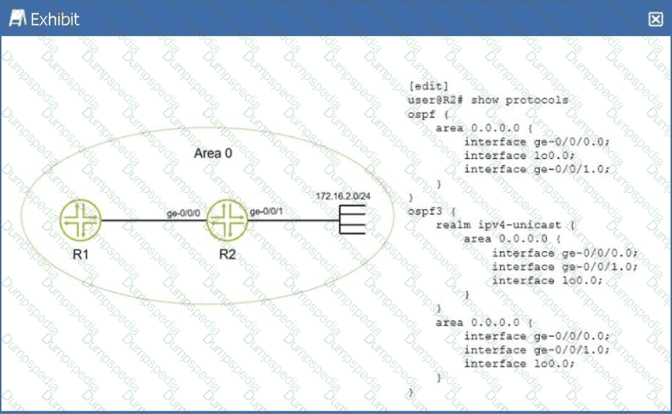
You have configured IPv4 and IPv6 in your network and all OSPF neighbors are established. You apply the configuration shown in the exhibit. Which statement is true in this scenario?
There will only be an OSPFv2 entry in R1 for network 172.16.2.0/24.
There will be an OSPFv2 and OSPFv3 entry in R1 for network 172.16.2.0/24.
There will not be a route in R1 for network 172.16.2.0/24.
There will only be an OSPFv3 entry in R1 for network 172.16.2.0/24.
In a Juniper Networks environment running Junos OS, understanding the interaction between different versions of OSPF is essential for multi-protocol environments.OSPFv2(defined in RFC 2328) is the standard protocol used for routing IPv4 unicast traffic.OSPFv3(defined in RFC 5340) was originally developed to support IPv6 routing. However, OSPFv3 was later extended via RFC 5838 to support multiple address families (AF), allowing it to carry IPv4 unicast, IPv4 multicast, and other address types within a single OSPF instance.
According to Juniper technical documentation, Junos OS implements this multi-AF support in OSPFv3 through the use ofrealms. When the realm ipv4-unicast statement is configured under the [edit protocols ospf3] hierarchy, the OSPFv3 process becomes capable of calculating and advertising IPv4 routes.
In the provided exhibit, routerR2has a dual-protocol configuration. First, it is running standard OSPFv2, with the ge-0/0/1.0 interface (which is directly connected to the 172.16.2.0/24 network) participating in Area 0. This ensures that the prefix is advertised as a standard IPv4 LSA to its neighbor,R1. Second, R2 is running OSPFv3 with the realm ipv4-unicast specifically enabled on that same ge-0/0/1.0 interface. Because of this realm, OSPFv3 also treats the 172.16.2.0/24 prefix as a reachable IPv4 destination and advertises it to R1 as an OSPFv3 IPv4-unicast LSA.
As a result, whenR1(which is also running both protocols) receives these routing updates, it will see the same destination prefix advertised by two different protocols. Its routing table (inet.0) will contain one entry learned from the OSPFv2 process and a second, separate entry learned from the OSPFv3 process. While the Junos Routing Engine will ultimately select one as the "active" route based on route preference (both protocols have a default preference of 10), both entries will technically exist within the Routing Information Base (RIB). This confirms that statementBis the correct description of the operational state of the network.
=========
You are configuring LDP in a service provider network. After enabling LDP on core interfaces, you notice that labels are being advertised for every loopback IPv4 address that is in your IGP. Which label distribution mode is being used in this scenario?
conservative retention
ordered control
downstream unsolicited
downstream on demand
In the context of theLabel Distribution Protocol (LDP), the method by which a router advertises labels to its neighbors is defined by itsLabel Advertisement Mode. According to Juniper Networks documentation and industry standards (RFC 5036), there are two primary modes:Downstream Unsolicited (DU)andDownstream on Demand (DoD).
InDownstream Unsolicited (DU)mode, which is the default behavior for Junos OS and most service provider implementations, an LSR (Label Switching Router) does not wait for a specific request from its neighbors. Instead, as soon as the LSR learns a prefix through its Interior Gateway Protocol (IGP) and establishes an LDP session, it automatically generates a label for that prefix and advertises it to all of its LDP peers. This explains the scenario where labels appear for every loopback address in the IGP as soon as LDP is enabled. DU mode is highly efficient for fast convergence because the labels are already present in the neighbors' databases before they are even needed for traffic forwarding.
By contrast,Downstream on Demand (DoD)requires a router to explicitly request a label for a specific prefix from its next-hop neighbor.Ordered Control (Option B)andIndependent Controlrefer to thetimingof label creation (whether a router waits for the next-hop to provide a label before creating its own), whileConservative Retention (Option A)refers to how a router stores labels it receives but doesn't currently use for forwarding. In the Junos default environment, LDP utilizesDownstream Unsolicitedadvertisement combined withOrdered ControlandLiberal Retentionto ensure a robust and rapidly converging MPLS control plane.
Which statement about RSVP-signaled LSPs is correct?
CSPF is not required for LSPs using admin-groups.
CSPF is used to calculate the path for a traffic-engineered LSP.
The paths used by LSPs are always calculated using the SRGB.
The paths used by LSPs are always calculated using the TED.
In a Juniper Networks environment,Resource Reservation Protocol (RSVP)is a signaling protocol used to establish Label-Switched Paths (LSPs). While RSVP handles the actual signaling (requesting labels and reserving bandwidth along a path), it does not inherently know which path to take. This is whereConstrained Shortest Path First (CSPF)comes into play.
CSPFis an advanced version of the Dijkstra algorithm used specifically for traffic engineering. Unlike the standard SPF used by IGPs, which only considers the shortest metric, CSPF takes into account multiple constraints such as available bandwidth, link coloring (administrative groups), and explicit hop requirements. According to Juniper technical documentation, when an LSP is configured, the Ingress router uses CSPF to calculate a loop-free path that satisfies all these constraints before RSVP begins signaling. This is why statementBis the correct description of the operational flow.
StatementDis a common distractor. While CSPF uses theTraffic Engineering Database (TED)to perform its calculations, the path is not "calculated by the TED" itself; the TED is merely the repository of link-state information (provided by OSPF or IS-IS extensions). StatementCrefers to Segment Routing Global Block (SRGB), which is relevant to Segment Routing (SR-TE), not standard RSVP-signaled LSPs. Finally, statementAis incorrect because admin-groups (link coloring) are actually one of the primary constraints thatrequireCSPF to determine a valid path.
Exhibit:

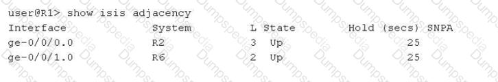
Referring to the exhibit, why is the ge-0/0/0.0 interface shown as belonging to Level 3?
This interface is configured as a point-to-point interface, that uses Level 3 as shorthand for both Level 1 and Level 2.
This interface is configured as a broadcast interface that has three adjacencies with other routers on the shared LAN.
This interface connects to a super spine.
This interface is configured as a broadcast interface, that uses Level 3 as shorthand for both Level 1 and Level 2.
In theIS-IS (Intermediate System to Intermediate System)protocol as implemented in Junos OS, the output of operational commands uses specific numerical representations to denote the hierarchy levels of a neighbor adjacency. Understanding these values is crucial for troubleshooting peering relationships in a multi-level IS-IS network.
According to Juniper Networks technical documentation, the show isis adjacency command displays the status of the neighbors. The "L" column indicates the level of the adjacency:
Level 1:Indicates the adjacency is strictly for intra-area routing.
Level 2:Indicates the adjacency is strictly for backbone/inter-area routing.
Level 3:This is ashorthand representationused by Junos to indicate that a single adjacency has been established forboth Level 1 and Level 2 simultaneously.
The critical distinction in this question lies in the interface type. On abroadcast interface(such as standard Ethernet), IS-IS typically establishes and maintains separate adjacencies for Level 1 and Level 2. In the CLI output for a broadcast link, you would generally see two separate lines for the same neighbor—one for Level 1 and one for Level 2.
However, on apoint-to-point (P2P)interface, IS-IS can negotiate both levels within a single adjacency. When this occurs, Junos consolidates the output into a single entry and usesLevel 3to signify that the adjacency is functional for both levels. Since the exhibit shows ge-0/0/0.0 as Level 3, it confirms that the link is configured with a point-to-point encapsulation (either natively or via the interface-type p2p command) and is acting as a Level 1/2 adjacency.
Option B is incorrect as the number "3" refers to protocol levels, not the count of neighbors. Option C is a reference to data center architectures that does not influence IS-IS level nomenclature. Option D is incorrect because, as noted, broadcast interfaces display these levels separately rather than using the Level 3 shorthand.
Which feature allows Junos OS to perform recursive lookups for static route next hops?
resolve
discard
reject
next-table
In standard routing, astatic routeis typically considered valid only if the specified next-hop IP address is directly reachable on a local subnet. However, in complex service provider designs, the next-hop might be a "distant" IP address that is reachable through another route (such as a BGP route or another static route). This process of looking up a next-hop within another routing entry is calledrecursive lookup.
In Junos OS, theresolve (Option A)parameter is explicitly used to enable this behavior for static routes. According to Juniper technical documentation, when you append the resolve keyword to a static route configuration, you are instructing the Routing Engine to search the routing table to find a path to that distant next-hop.
For example:
set routing-options static route 10.1.1.0/24 next-hop 192.168.100.1 resolve
If 192.168.100.1 is not on a local interface but is reachable via an OSPF route, the router will "resolve" the path and install the 10.1.1.0/24 route into the forwarding table using the OSPF path's exit interface.
Why other options are incorrect:
Discard (Option B)andReject (Option C)are "next-hop types" used to drop traffic, either silently (discard) or by sending an ICMP unreachable message (reject).
Next-table (Option D)is used forInter-VRF routing, where the router is told to look up the destination in a completely different routing instance (like a VRF table), which is a different architectural function than a recursive next-hop lookup within the same table.
A service provider is onboarding a new enterprise customer that operates multiple branch offices, each with its own set of VLANs. The customer requires transparent Layer 2 connectivity between sites while maintaining separation of internal VLANs. The provider must also ensure that customer VLAN identifiers do not conflict with other customers on the shared infrastructure. Which solution would provide the desired results?
Extend customer VLANs using Q-in-Q tunneling.
Deliver Layer 3 VPN services using MPLS.
Aggregate customer traffic using GRE tunnels.
Provide Internet access with NAT and firewall services.
In a service provider environment,Q-in-Q tunneling(also known as 802.1ad or double-tagging) is the standard solution for transporting multiple customer VLANs over a shared provider backbone while maintaining total separation.
According to Juniper Networks documentation, Q-in-Q works by adding a second 802.1Q tag (theService Provider tagor S-tag) to the customer’s already tagged frames (theCustomer tagor C-tag). This creates a "tunnel" at Layer 2. This solution specifically addresses all the customer's requirements:
Transparent Layer 2 Connectivity:Because the provider simply encapsulates the customer's frames, the customer's internal BPDU traffic (like Spanning Tree) and VLAN tags are preserved and delivered transparently to the remote site.
Separation of Internal VLANs:The customer can run their own internal VLAN IDs (1-4094) without the provider needing to know or manage them.
Conflict Avoidance:Different customers on the same provider infrastructure are assigned unique S-tags. Even if two different customers both use "VLAN 10" internally, they remain isolated because their traffic is encapsulated in different provider S-tags.
Why other options are incorrect:
Layer 3 VPN (Option B):While MPLS L3VPNs are common, they provide Layer 3 (IP) connectivity, not the "transparent Layer 2" connectivity requested.
GRE Tunnels (Option C):GRE is a Layer 3 encapsulation and does not natively provide the transparent VLAN bridging required for a multi-site Layer 2 service.
NAT/Firewall (Option D):These are security and address-translation services for internet access and do not facilitate site-to-site Layer 2 bridging.
What happens if an IS-IS router receives a link-state PDU with a higher sequence number than the one in its database?
It ignores the link-state PDU.
It updates its database and floods the link-state PDU.
It sends a CSNP to request confirmation from the source of the link-state PDU.
It resets the adjacency with the source of the link-state PDU.
IS-IS is a link-state protocol that relies on the rapid and consistent flooding ofLink-State PDUs (LSPs)to ensure that every router in an area has an identical view of the topology. To manage the "freshness" of information, IS-IS uses aSequence Number—a 32-bit unsigned integer that increments every time the originating router makes a change to its LSP.
According to Juniper Networks technical documentation, when a router receives an LSP, it performs a comparison between the received LSP and the version it currently holds in itsLink-State Database (LSDB). If the received LSP has ahigher sequence number, the router concludes that this is "newer" and more accurate information. The router will then perform two immediate actions:
Update:It replaces the older LSP in its LSDB with the newly received version.
Flood:It propagates the new LSP to all other neighbors (except the one that sent it) to ensure the entire area converges on the new data.
If the sequence numbers were equal, the router would ignore the incoming PDU as it already has the information. If the received sequence number werelower, the router would conclude its own database is more recent and would actually send its own "newer" version back to the neighbor to bring them up to date (a process called "poisoning" or refreshing the neighbor).Complete Sequence Number PDUs (CSNPs)(Option C) are used during initial database synchronization or periodic checks on broadcast links, but the primary response to a "newer" LSP is immediate database update and flooding.
TESTED 28 Feb 2026

