dumpspedia logo

How can an electrical designer see changes from other users without saving their own work to the central model?
Relinquish All Mine
Reload Latest
Manage Worksets
Worksharing Display
In Autodesk Revit, particularly for electrical and MEP design disciplines using a workshared model, the command “Reload Latest” allows a designer to see changes made by other users without saving or publishing their own work to the central model. This tool ensures that while the designer continues to work locally, their environment stays updated with the latest modifications made by colleagues.
According to the Autodesk Revit MEP User Guide (Chapter 54 – Working in a Team), under the section Loading Updates from the Central Model, it states:
“As you work, you can see the changes other team members have made to the project after they have been synchronized with the central model. You can load updates from the central model without publishing your changes to the central model.
In your local file, click Collaborate tab ➤ Synchronize panel ➤ (Reload Latest).”
This confirms that the Reload Latest command refreshes your local file with any modifications from the central file that others have synchronized, but it does not send your local changes back. It is a critical feature for coordination in a team environment, especially when multiple designers—such as electrical, mechanical, and structural engineers—are contributing simultaneously to a shared BIM model.
By contrast:
A. Relinquish All Mine only releases ownership of elements but doesn’t update the local model.
C. Manage Worksets is for controlling visibility and editability of worksets.
D. Worksharing Display visually identifies ownership and status but doesn’t refresh model data.
Therefore, when an electrical designer needs to review updates from others (for example, when a lighting layout needs coordination with architectural ceiling adjustments), the proper workflow is to use Reload Latest, ensuring all new information from the central model appears instantly without saving or affecting their current unsaved edits.
Refer to exhibit.
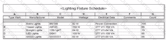
Which two actions were used to create this light fixture schedule? (Select two.)
Deselected Itemize every instance.
Filtered to only show lights that have a type mark value.
Added both electrical and switch system settings.
Sorted by type mark.
Sorted by instance and quantity.
In the given Lighting Fixture Schedule, each row represents a lighting fixture type rather than individual instances, and the “Count” column summarizes how many fixtures of that type exist in the project. To achieve this layout in Revit, two specific actions must be performed in the Schedule Properties dialog:
Deselected “Itemize every instance.”
The Revit documentation explains:
“Itemize every instance. This option displays all instances of an element in individual rows. If you clear this option, multiple instances collapse to the same row based on the sorting parameter. If you do not specify a sorting parameter, all instances collapse to one row.”
By deselecting this checkbox, Revit consolidates identical fixture instances of the same type into a single row — exactly as shown in the exhibit, where each “Type Mark” (A, B, C, etc.) appears once with a summarized Count.
Sorted by Type Mark.
On the same Sorting/Grouping tab, Revit allows users to organize the schedule by a specific field:
“On the Sorting/Grouping tab of the Schedule Properties dialog, you can specify sorting options for rows in a schedule… You can sort by any field in a schedule, except Count.”
In the example, fixtures are sorted alphabetically by their “Type Mark” (A through E). This ensures the grouped and counted results appear in order.
Other options—such as filtering by type mark or adding switch data—do not impact how instances collapse or group within the schedule.
Which feature shows which user created 3n element?
Gray Inactive Worksets
Worksharing display modes
Show History
Worksets dialog
In Autodesk Revit, the Worksharing Display Modes feature allows designers to visually inspect ownership and editing information about elements in a workshared model.
According to the Autodesk Revit MEP User Guide – Chapter 54 “Working in a Team”:
“Worksharing Display Modes can be used to visualize the ownership of elements, including which user created or modified them. For example, you can use the Worksharing Display command to show elements by their owner, workset, or checkout status.”
Thus, this mode identifies which user created or owns an element — making B. Worksharing display modes the correct choice.
Other options:
A. Gray Inactive Worksets: Only shows non-active worksets in gray, not creator info.
C. Show History: Displays synchronization comments, not element ownership.
D. Worksets dialog: Shows ownership of worksets, not individual elements.
An electrical designer has noticed lighting fixtures present in an architectural linked model. Which tool should be used to place an instance of those fixtures in the current electrical model while maintaining the position from the architectural model?
Copy/Monitor
Coordination Review
Reconcile Hosting
Reload Latest
When lighting fixtures placed in an architectural linked model need to be replicated in the electrical model while maintaining their exact positions, the correct tool is Copy/Monitor.
This Revit feature allows the electrical designer to copy elements—like lighting fixtures—from a linked model into their project, while establishing a monitoring relationship between the original (architectural) and copied (electrical) instances.
From the Autodesk Revit MEP User’s Guide – Chapter 55 “Multi-Discipline Coordination” (pages 1349–1357):
“Use the Copy/Monitor tool to copy MEP fixtures from an architectural model into an MEP project, and monitor them for changes.”
(Revit MEP User’s Guide, p. 1350)
“To copy fixtures from a linked model:
Click Collaborate tab ➤ Coordinate panel ➤ Copy/Monitor ➤ Select Link.
Select the linked architectural model in the drawing area.
Click Copy and select the lighting fixtures to copy.
Click Finish.Revit MEP copies the fixtures to the current project and establishes monitoring relationships.”*(Revit MEP User’s Guide, p. 1356)
Behavior and Benefits:
The copied lighting fixtures maintain the same location, orientation, and type mapping as in the linked model.
Any changes (move, delete, or modify) made by the architect in the linked model will trigger a coordination review in the electrical model.
This ensures accurate positioning and easy coordination between disciplines.
“When you select a copied fixture in the current project, the monitor icon displays next to the fixture, indicating that it has a relationship with the original fixture in the linked model.”
(Revit MEP User’s Guide, p. 1357)
“If copied fixtures are moved, changed, or deleted in the linked model, Revit MEP notifies the engineers of the changes during Coordination Review.”
(Revit MEP User’s Guide, p. 1357)
How can an arrowhead be added to a lag leader line?
Change the Leader Type to Free End.
Enable Leader Arrowhead in the instance properties.
Choose an arrow type for the Leader Arrowhead in the Type Properties.
Select the tag and enable Leader Line in the Properties palette
In Autodesk Revit for Electrical Design, arrowheads on leader lines—such as those used with tags, text notes, or annotations—are controlled through Type Properties, not through instance properties or free-end options.
According to the Revit MEP User’s Guide – Annotating Chapter (Chapter 47 and 42), the section “Modifying Tags” explains:
“Select the tag, and on the Properties palette, click (Edit Type). In the Type Properties dialog, select a value for Leader Arrowhead to add an arrowhead to the leader line.”
This confirms that the arrowhead is defined at the type level, meaning any change applies to all tags or text notes of that annotation type throughout the project. The Leader Arrowhead property allows the designer to choose from predefined arrowhead styles (like “Filled Arrow,” “Dot,” “Tick Mark,” etc.), which are defined globally under:
Manage tab → Settings panel → Additional Settings → Arrowheads.
Furthermore, the document specifies under “Leader Arrowhead Properties”:
“Sets the arrowhead shape on the leader line. The value is the name of the arrowhead style defined by the Arrowheads tool.”
This behavior applies to all annotation categories, including text notes, keynotes, material tags, and electrical device tags, maintaining consistency across all view types in an electrical project.
Therefore, Option C is the correct answer because arrowheads are configured via Type Properties, while the other options are inaccurate:
Option A (Free End) only defines leader attachment behavior.
Option B (Instance properties) does not include a “Leader Arrowhead” toggle.
Option D (Enable Leader Line) only adds or removes a leader line, not the arrowhead style.
Refer to exhibits.
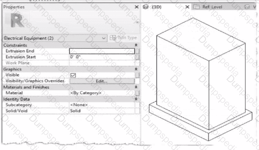
When loaded into a project, the family displays as below in plan view.
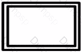
The electrical designer is satisfied with the line color and weight of the transformer because it matches all other electrical equipment in the project. However, the designer wants the housekeeping pad to display with different line properties as shown below.
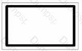
How can this be achieved?
An electrical designer creates a simple family of a transformer with a concrete housekeeping pad using two rectangular extrusions. Both extrusions and their properties within the family editor are shown.
Within the family editor, select the housekeeping pod object and change it from a solid to a void.
Within the project, right-click and select Override Graphics in View from the context menu. Edit the line properties as desired.
Within the family editor, create a new object style subcategory with the desired properties. Assign that subcategory to the housekeeping pad object.
Within the family editor, right-click the housekeeping pad object and select Visibility from the context menu. Edit the line properties as desired.
In Autodesk Revit Electrical Design, when customizing a family—such as a transformer with a housekeeping pad—each element within the family can have its own subcategory under the parent category (in this case, Electrical Equipment). Subcategories are critical for controlling line weight, color, and material properties independently in project views and visibility settings.
The issue described is that the transformer and its concrete pad currently share the same default category (Electrical Equipment) and therefore use identical line weights and colors in plan view. The designer wants the housekeeping pad to display differently — for example, with a lighter or dashed outline.
According to the Autodesk Revit MEP User’s Guide (Chapter: Creating and Editing Families):
“To control the visibility or graphical appearance of individual components within a family, create a new Object Styles subcategory under the parent category. You can then assign any solid or void geometry in the family to that subcategory. When loaded into a project, the subcategory can be independently controlled through Visibility/Graphics (VG) settings.”
This is the exact and recommended workflow for differentiating line appearances between elements in the same family.
Steps to achieve this:
In the Family Editor, open Manage tab ➤ Object Styles.
Under the Model Objects tab, click New to create a new subcategory (e.g., “Housekeeping Pad”).
Set the desired line weight, color, or material properties.
Select the housekeeping pad extrusion in the model.
In the Properties palette, under Identity Data → Subcategory, choose Housekeeping Pad.
Reload the family into the project.
You can now modify or control its visibility independently in project views.
Why the other options are incorrect:
A. Change to void: A void removes geometry, not graphical appearance.
B. Override Graphics in View: Applies only in a single view, not globally across the project.
D. Visibility from context menu: Controls whether the object is visible, not its line properties.
Thus, the most efficient, parametric, and Revit-standard method is to use subcategories within the family to apply distinct graphical controls.
Refer to exhibit.
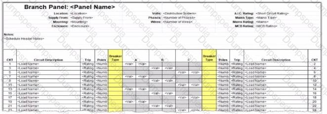
An electrical designer wants to report Breaker Type for each breaker in a panel schedule. The designer adds a column to the schedule as shown (and highlighted) in the image.
Which type of parameter should the designer create to add to the column?
A Shored Parameter in the Electrical Equipment families.
A Shared Parameter in the Electrical Fixture families.
A Project Parameter assigned to Electrical Circuits.
A Project Parameter assigned to Electrical Equipment.
In Autodesk Revit Electrical Design, panel schedules display data that originates from the Electrical Circuits category, not directly from the Electrical Equipment or Electrical Fixtures families. Each circuit in a panel schedule represents an instance of an Electrical Circuit object within Revit’s system-based MEP structure. Therefore, to add an additional field like Breaker Type, the parameter must be created and assigned specifically to the Electrical Circuits category.
According to the Revit MEP User’s Guide – Chapter 50 “Electrical Systems and Panel Schedules”:
“Panel schedules display parameters that are associated with electrical circuits, including load names, rating, poles, and breaker information. To include additional circuit information in a panel schedule, create a Project Parameter assigned to the Electrical Circuits category.”
This means the designer should:
1️⃣ Open Manage → Project Parameters → Add
2️⃣ Create a Project Parameter named Breaker Type
3️⃣ Assign it to the Electrical Circuits category
4️⃣ Set it to appear in schedules and tags, ensuring it becomes available for use in the panel schedule template
As noted in the Smithsonian Facilities Revit Template User’s Guide:
“Custom circuit data fields such as ‘Breaker Type’ or ‘Wire Tag’ are defined as project parameters applied to the Electrical Circuits category so they can be displayed in panel schedule templates.”
Incorrect options:
A. Shared Parameter in Electrical Equipment — Electrical Equipment holds overall panel data (e.g., Mains Rating, Voltage) but not per-circuit data.
B. Shared Parameter in Electrical Fixture families — Fixtures are individual load devices, not part of the circuit’s breaker assignment.
D. Project Parameter assigned to Electrical Equipment — would apply to the panelboard as a whole, not to individual breakers in circuits.
Thus, the correct answer is C. Project Parameter assigned to Electrical Circuits, ensuring each breaker in the panel schedule can display its type individually and dynamically.
Refer to exhibit.
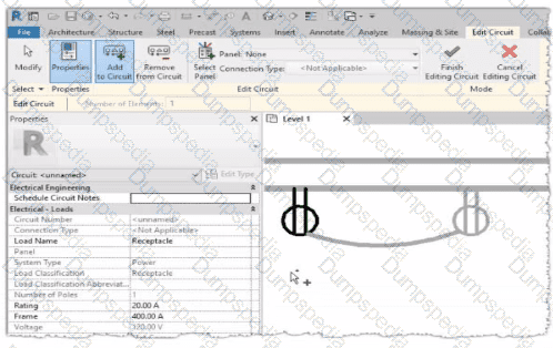
Why is one receptacle shown in full color (black) and one receptacle shown in halftone (gray)?
The circuit's panelboard is not assigned.
The two receptacles are not on the some circuit.
The wire connecting the two receptacles is not property attached
The two receptacles have different load classifications.
In Autodesk Revit MEP, when working with electrical circuits, Revit visually differentiates elements based on their circuit membership and active selection during the circuit editing process. In the Edit Circuit mode, the software highlights elements connected to the active circuit in full color (black), while other electrical devices not part of that same circuit appear in halftone (gray).
In the exhibit, one receptacle appears in black, while the other is shown in gray (halftone). This indicates that only one of the receptacles is currently included in the circuit being edited, while the other receptacle belongs to a different circuit or has not yet been assigned to any circuit.
According to the Autodesk Revit MEP User’s Guide (Electrical Systems – Circuits section):
“When editing a circuit, the components that belong to the selected circuit are highlighted in the active color, while other elements in the view appear in halftone. Devices that are not on the same circuit will not be shown as connected or editable until added to the current circuit.”
Therefore:
The black receptacle is the one actively included in the selected circuit.
The gray (halftone) receptacle is not on the same circuit and thus not active for editing.
This visual cue is Revit’s way of helping the designer distinguish between circuit connections when adding or managing electrical devices.
An electrical designer needs to add a drafting view to a model from another project. What is the method to do this?
Select Transfer Project Standards, select the desired project, and then select the drafting view.
Select Open, select the desired project, right-click the desired drafting view, and then copy/paste
Select Link Revit, browse to the desired model, and then select desired drafting view
Select Insert from File, select Insert Views from File, browse to the desired project, and then select the drafting view.
In Autodesk Revit, a drafting view is a 2D view that contains detail information not directly associated with the model. When an electrical designer needs to reuse a drafting view from another project (for example, standard details or symbols), the correct method is to use the Insert Views from File command under the Insert tab.
The Autodesk Revit MEP User’s Guide – Chapter 48 “Detailing” (page 1072) describes the process as follows:
“Inserting a Drafting View from Another Project
Click Insert tab ➤ Import panel ➤ Insert from File drop-down ➤ Insert Views from File.
In the Open dialog, select a project file, and click Open.
The Insert Views dialog opens, displaying all the views that are saved in that project.
Select the desired drafting views and click OK.”(Revit MEP User’s Guide, p. 1072)
This command imports the drafting view into the current Revit model while preserving annotations, filled regions, detail components, and text. It ensures that any standard electrical symbols, notes, or schematics created previously can be directly reused without rebuilding the detail from scratch.
If any duplicate type names exist, Revit automatically uses the types and properties from the current project, displaying a warning if necessary.
“Revit MEP creates a new drafting view with all the 2D components and text. If you have duplicate type names, the type name and properties from the current project are used.”
(Revit MEP User’s Guide, p. 1072)
Supporting Documentation Extracts:
“Saving Drafting Views to an External Project
Select a drafting view in the Project Browser.
Right-click the view name, and click Save to New File.”(Revit MEP User’s Guide, p. 1071)
“The saved project can then be used later to insert drafting views into another Revit project using Insert Views from File.”
(Revit MEP User’s Guide, p. 1072)
Refer to exhibit.
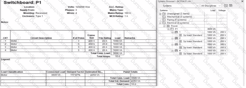
An electrical designer expects the total connected load on the switchboard to be 4000VA. but Revit Indicates a total connected load of 3606VA. What Is the cause of the discrepancy?
The connected loads are set to a different voltage than the switchboard.
The Motor demand factor is configured to adjust the connected load.
Load is connected through the switchboard's feed through lugs.
Sum true load and reactive load is selected in Electrical Settings.
In the exhibit, the designer expects the total connected load to equal the sum of the 4 motor loads:
4 motors × 1000 VA each = 4000 VA expected
However, Revit is showing a Total Connected Load of 3606 VA instead.
This difference occurs because Revit applies Motor Demand Factors automatically when a load classification is set to “Motor.” Demand factors modify the total connected load based on electrical engineering rules.
Revit documentation confirms:
“Assign demand factors to load classifications.”
“Demand loads can be shown on panel schedules.”
In the exhibit, the Load Classification shows Motor with a Demand Factor of 117.87%, which modifies the connected load values in the switchboard totals.
Revit is therefore calculating the effective connected load based on the applied demand factor, not a simple arithmetic sum. That is why the panel’s connected load number ≠ 4000 VA.
Refer to exhibit.
(The Image is presented in Imperial units: 1 In = 25 mm [Metric units rounded).)

What is the electrical designer trying to do as shown in the exhibit?
Add Cable Tray
Place Parallel Conduits
Array Conduit
Place Multiple Pipe
The exhibit shown in the image is taken directly from the Revit MEP Electrical Systems workspace, specifically from the Parallel Conduits command interface. This dialog box appears when the designer activates the Place Parallel Conduits tool in the Systems tab → Electrical panel → Conduit dropdown → Parallel Conduits.
In this interface, the designer can specify:
Horizontal Number / Offset – defines how many conduits will be created horizontally and their spacing.
Vertical Number / Offset – defines how many conduits will be created vertically and their spacing.
Bend Radius Options:
Same Bend Radius – all conduits use identical bend radii.
Concentric Bend Radius – conduits bend concentrically around a common center point.
According to Autodesk’s Revit MEP 2011 User’s Guide (Chapter 18, Electrical Systems – Conduit Layout):
“The Parallel Conduits tool allows you to create multiple conduits side-by-side at the same time.
You can specify the number of conduits horizontally and vertically, as well as the offset between them.
You can also define whether bends have the same bend radius or concentric bend radii.”
— Revit MEP User’s Guide, Electrical Systems, Section: Conduit Layout
This tool is used when electrical designers need to route groups of conduits that run in parallel—such as power and data conduits running between panels or equipment racks.
The Concentric Bend Radius option (as shown in the exhibit) ensures all conduit bends share a common center, which is critical for maintaining uniformity in conduit sweeps and avoiding clashes during coordination.
Therefore:
A. Add Cable Tray – incorrect; the cable tray tool is separate and does not use bend radius options.
C. Array Conduit – incorrect; arraying is a different geometric function not specific to conduit routing.
D. Place Multiple Pipe – incorrect; applies to mechanical piping systems, not electrical conduits.
The display of Concentric Bend Radius, Horizontal Number, Vertical Number, and Offset confirms that the designer is using the Parallel Conduit placement tool.
Verified Reference Extracts from Revit Electrical Design Documentation:
Autodesk Revit MEP User’s Guide (2011) – Electrical Systems → Conduit Layout → “Parallel Conduits Tool” description.
Autodesk Revit MEP Training Curriculum – Electrical Module, Exercise 6.3 “Placing Parallel Conduits,” which illustrates the same interface for bend radius configuration.
Refer to exhibit.
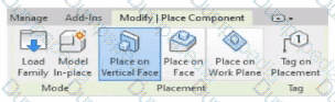
An electrical designer is placing electrical equipment. When the electrical designer selects a component in the contextual ribbon, the Placement panel appears in the contextual ribbon.
Which condition does this Placement panel indicate?
The component was created using a lace-based template.
The component was created using a wall-based template
The component was created using a floor-based template.
The component is set to use the Always Vertical option
The Placement panel shown in the exhibit — with options such as Place on Vertical Face, Place on Face, and Place on Work Plane — is displayed only when the family being placed was created using a wall-hosted (face-based or vertical face-based) template. This indicates that the family is designed to be hosted on a vertical surface, such as a wall, rather than a floor or level.
According to the Autodesk Revit MEP User’s Guide (Chapter 44 “Creating and Modifying Families”):
“When placing a hosted family, the placement options depend on the family’s host type.
Wall-based families display the Place on Vertical Face option.
Ceiling-based families display Place on Face or Place on Work Plane.
Floor-based families display Place on Work Plane only.”
The “Place on Vertical Face” option specifically appears for wall-hosted or face-based components because it allows the user to select a vertical plane, typically representing a wall surface. This confirms that the family template used during creation was Wall-based (commonly “Electrical Equipment - Wall Based.rft” or “Generic Model - Wall Based.rft”).
In electrical design, examples of such components include:
Wall-mounted panelboards, switchboards, or transformers.
Receptacles or lighting control devices hosted on walls.
The Smithsonian Facilities Revit Template Guide reinforces this explanation:
“Wall-based components, such as surface-mounted panels, display the Place on Vertical Face option. This confirms the family is wall-hosted and cannot be placed freely on floors or reference planes.”
Why the Other Options Are Incorrect:
A. Face-based template: Would show “Place on Face” (not necessarily limited to vertical).
C. Floor-based template: Displays “Place on Work Plane” only.
D. Always Vertical option: Controls orientation (rotation relative to surface), not placement host type.
Therefore, the Placement panel confirms the component was created using a wall-based family template, allowing it to be attached only to vertical surfaces.
An electrical designer wants to add a parameter to a lighting fixture schedule without editing the families. Which parameter type should the designer use?
Schedule parameter
Project parameter
Global parameter
Family parameter
In Revit Electrical Design workflows, when a designer wishes to add a parameter to a lighting fixture schedule without editing the families themselves, the proper approach is to use a Project Parameter.
The Revit MEP documentation clearly explains:
“To add a custom field to a schedule, you can create a custom parameter using the Parameter Properties dialog. Under Parameter Type, select Project parameter.”
This method links the parameter directly to the project and to all instances of the specified category (in this case, Lighting Fixtures), allowing it to appear in the schedule automatically without requiring any modification to the family files (.RFA).
In contrast:
Family Parameters apply only within the family file and are not schedulable across multiple families.
Global Parameters control dimensional or relational constraints, not schedule data.
Reporting Parameters are read-only and extract model information; they cannot be manually added to schedules.
Revit’s scheduling workflow defines this process:
“On the Fields tab of the Sheet List Properties dialog, click Add Parameter… Under Parameter Type, select Project parameter.”
This same mechanism applies to lighting fixture schedules, as schedules and sheet lists share parameter structures in Revit. The new project parameter can then be sorted, filtered, and displayed in the schedule view for documentation or tagging purposes.
An electrical designer is trying to adjust the scale of a view. All icons on the View Control Bar are dimmed (not enabled). How should the designer make the view scale editable only for this view?
Set the view template to
Edit the assigned view template.
Duplicate the view with Detailing.
Right-click on the scale and select
When all icons on the View Control Bar are dimmed (disabled), including the View Scale, it typically means the view is being controlled by a View Template. View templates apply standardized settings—such as scale, discipline, detail level, and more—across multiple views to ensure consistency. However, these templates can lock certain parameters, including the view scale, preventing manual changes.
According to Revit Electrical Design standards:
"If a view is governed by a View Template, properties such as view scale may be locked and appear dimmed in the View Control Bar. To regain control and allow changes like adjusting the view scale, the view template must be removed. This is done by setting the View Template to <None> in the Properties Palette."
Steps:
Select the view in question.
Open the Properties Palette.
Locate the View Template parameter.
Set it to <None>.
Now the View Control Bar becomes active and the scale can be changed freely.
Clarification of Other Options:
B (Edit the assigned view template): Changes apply to all views using that template, not just the one.
C (Duplicate the view with Detailing): Creates a copy but doesn't resolve template restrictions.
D (Right-click on the scale and select <Activate>): This is not a valid method in Revit.
Refer to exhibit.
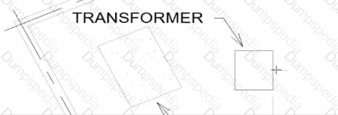
An electrical designer wants to place electrical equipment on the pad.
How should the component be aligned to the pad before placement?
Start the Align tool. tab to select the object edge, and then select the equipment edge.
Start the Align tool and select the edges to be aligned.
Place the cursor over an edge of the object and then press Spacebar.
Place the cursor anywhere over the object and then press Spacebar.
In Autodesk Revit, when placing electrical equipment such as transformers, disconnects, or switchboards onto a pad or foundation, precise alignment is essential for accurate coordination with architectural and structural elements. During component placement, Revit provides an intuitive way to align an object before final placement using the Spacebar in combination with the object’s edges.
When the cursor is hovered over an edge of the component (not just anywhere on it) and the Spacebar is pressed, Revit cycles the component’s orientation, rotating it 90 degrees around its insertion point each time. This technique allows the designer to visually align the equipment’s orientation with the pad or architectural geometry before clicking to place it.
According to the Autodesk Revit MEP User’s Guide under “Placing and Modifying Components”:
“While placing a component, move the cursor over an edge and press the Spacebar to rotate the element incrementally. This method helps align electrical or mechanical equipment with nearby reference geometry before placement.”
This method is ideal for electrical designers positioning pad-mounted equipment, ensuring that components such as transformers or switchgear are oriented precisely to site geometry, conduit routes, or building walls.


TESTED 14 Oct 2026